Prefabricated steel rib-concrete combined shear wall splicing device and application method

A technology of prefabricated concrete and combined shear walls, which is applied in the direction of construction and building construction, can solve the problems of potential safety hazards, low rigidity outside the steel plate surface, and easy instability, so as to save construction period, solve construction safety problems, and ensure The effect of construction quality

Pending Publication Date: 2019-02-19
SHANDONG UNIV
View PDF10 Cites 5 Cited by
  • Summary
  • Abstract
  • Description
  • Claims
  • Application Information

AI Technical Summary

Problems solved by technology

The splicing method of the upper and lower walls of the steel plate concrete composite shear wall is mainly steel plate welding, and the out-of-plane rigidity of the steel plate is extremely low, which is prone to instability during the construction process, posing a great safety hazard

Method used


Image

  • Prefabricated steel rib-concrete combined shear wall splicing device and application method
  • Prefabricated steel rib-concrete combined shear wall splicing device and application method
  • Prefabricated steel rib-concrete combined shear wall splicing device and application method

Examples


Embodiment 1

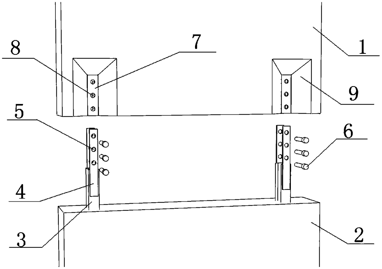
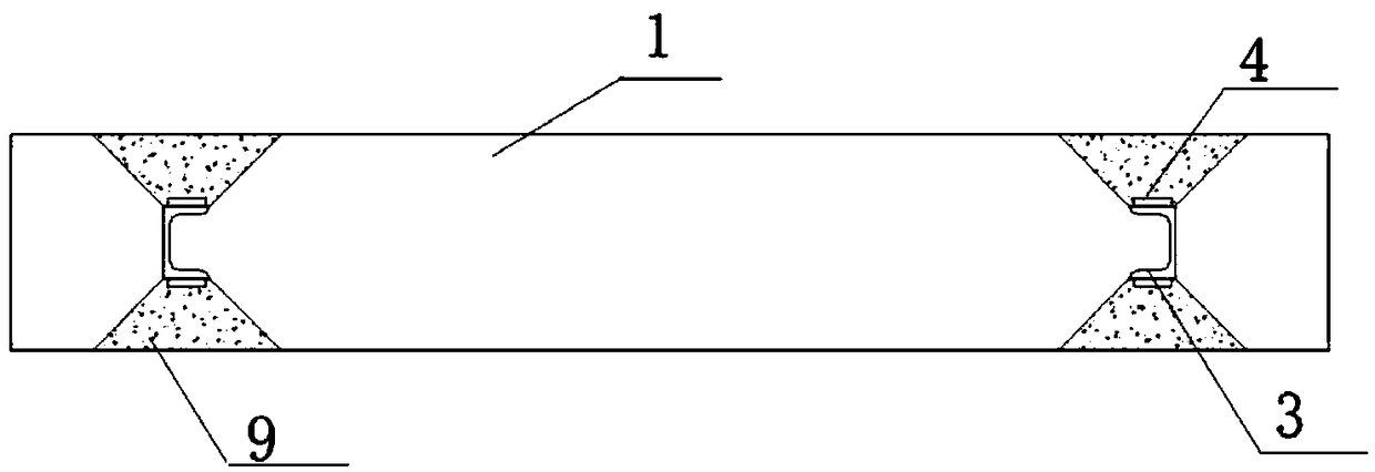
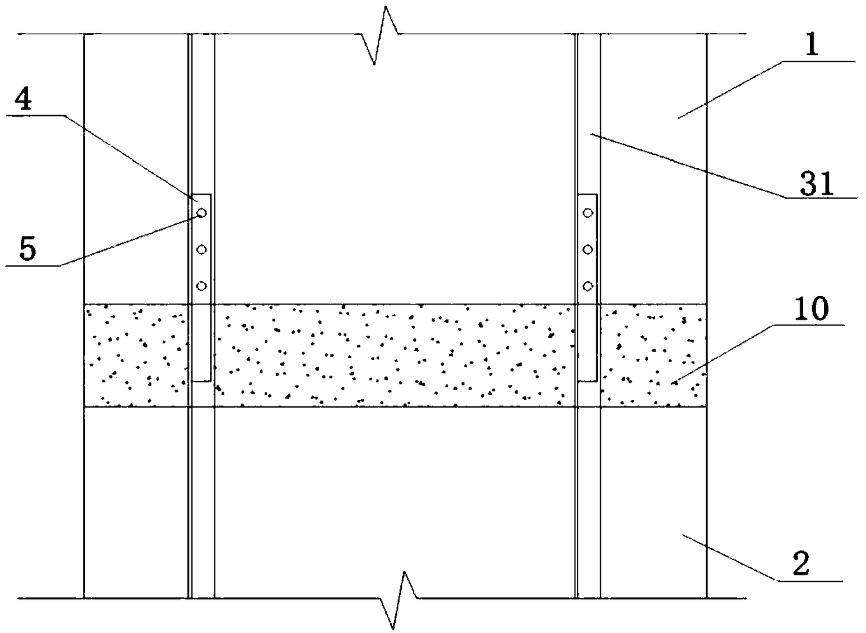
[0063] Such as Figure 1-6 As shown, a prefabricated steel frame-concrete composite shear wall splicing device includes: an upper precast concrete wall 1, a lower precast concrete wall 2, a lower pre-embedded steel frame 3, splicing steel plates 4, and reserved holes 5 for splicing plates , cross-piercing bolts 6, upper pre-embedded steel frame 7, reserved holes 8 for pre-embedded steel frame and wedge-shaped post-casting area 9.

[0064] One end of the lower pre-embedded steel frame 3 is arranged in the end face of the lower precast concrete wall 2 in the thickness direction, and the other end is fixedly connected with the spliced ​​steel plate 4; and each lower pre-embedded steel frame 3 corresponds to two spliced ​​steel plates 4, each The two are respectively symmetrically connected to both sides of the flange of the lower pre-embedded steel frame 3; after the connection, the distance between the two spliced ​​steel plates 4 is used to accommodate the vertically inserted u...

Embodiment 2

[0073] Such as Figure 7-10 As shown, a prefabricated steel frame-concrete composite shear wall splicing device is the same as that in Embodiment 1, the difference is that: the lower pre-embedded steel frame 3 and the spliced ​​steel plate 4 are connected by welding, and the width of the spliced ​​steel plate 4 should be Less than the width of the lower pre-embedded steel frame 3, to ensure the width of the weld seam after welding, and avoid the welding seam being too small to cause insufficient welding strength between the lower pre-embedded steel frame 3 and the spliced ​​steel plate 4.

Embodiment 3

[0075] Such as Figure 11-15 As shown, a prefabricated steel frame-concrete composite shear wall splicing device is the same as that in Embodiment 1, the difference is that the spliced ​​steel plate 4 shown is connected to the center of the web of the lower pre-embedded steel frame 3 .


PUM


Abstract

The invention relates to a prefabricated steel rib-concrete combined shear wall splicing device and an application method, and belongs to the technical field of fabricated buildings. Reserved wedge-shaped post-pouring areas are arranged at the lower parts of splicing steel plates and a prefabricated shear wall, the lower ends of steel ribs in an upper prefabricated concrete wall body and the lowerend of the prefabricated concrete wall body are flush, the wedge-shaped post-pouring areas are arranged at the lower end of the wall body, the steel ribs in the wall body are exposed, and concrete pouring is carried out to level after the splicing is completed; the upper ends of steel ribs in a lower prefabricated concrete wall body extend out of the prefabricated concrete wall body, and the upper ends of the steel ribs are connected with the splicing steel plates for being connected with the steel ribs in the upper prefabricated wall body; the splicing steel plates can be connected to both sides of flanges of the steel ribs or middle web plates of the steel ribs; and the wedge-shaped post-pouring areas are arranged at the lower end of an upper layer prefabricated concrete wall. Accordingto the prefabricated steel rib-concrete combined shear wall splicing device and the application method, the shear wall can be directly placed on a floor slab, and the self-weight of the wall body andthe construction load do not act on splicing joints, so that the construction quality of the joints is ensured, and the construction safety problem is effectively solved.

Description

technical field [0001] The invention belongs to the technical field of prefabricated buildings, and in particular relates to a prefabricated steel frame-concrete composite shear wall splicing device and an application method. Background technique [0002] At present, the main structural form of high-rise prefabricated buildings is the shear wall structure, and the shear wall is the basic component of the shear wall structure system, mainly including reinforced concrete shear walls and steel-concrete composite shear walls. The traditional splicing of reinforced concrete shear walls is to connect the longitudinal bars of the upper and lower walls through sleeves, and then inject grout into the sleeves to realize the connection. In the actual construction process, the longitudinal reinforcement is often difficult to align due to construction errors. At the same time, the connection quality of the grouting sleeve will also be uneven, which leads to the construction quality of th...

Claims


Application Information

Patent Timeline
Patent Type & Authority Applications(China)
IPC IPC(8): E04B1/04E04B1/61
CPCE04B1/043E04B1/6141
Inventor 王培军孙乐乐刘泽新韩飞丁一婧
Owner SHANDONG UNIV
Why Eureka
Try Eureka