Grating detection system for low reflection energy transmission fiber grating and method
An energy optical fiber and grating detection technology, applied in transmission systems, optical instrument testing, electromagnetic wave transmission systems, etc., can solve problems such as limited detection distance, grating crosstalk, and complex system structure, so as to improve recognition rate and accuracy and avoid recognition Difficulty, the effect of improving the signal-to-noise ratio
- Summary
- Abstract
- Description
- Claims
- Application Information
AI Technical Summary
Problems solved by technology
Method used
Image
Examples
Embodiment 1
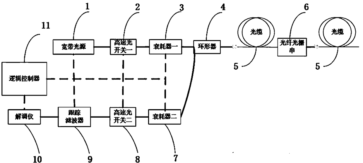
[0050] In a specific embodiment, the present invention provides a low reflection energy fiber grating detection system, the system includes: a broadband light source, a high-speed optical switch 1, an attenuator 1, a circulator, an optical cable, a fiber grating string, an attenuator Consumer II, high-speed optical switch II, tracking filter, demodulator and logic controller;
[0051] The broadband light source, high-speed optical switch 1, and attenuator 1 are connected to the circulator; the demodulator, tracking filter, high-speed optical switch 2, and attenuator 2 are connected to the circulator; the circulator is connected to the optical cable , the fiber grating is placed in the optical fiber of the optical cable; the logic controller is respectively connected with the broadband light source, the high-speed optical switch one, the attenuator one, the attenuator two, the high-speed optical switch two, the tracking filter and the demodulator , and carry out logic control t...
Embodiment 2
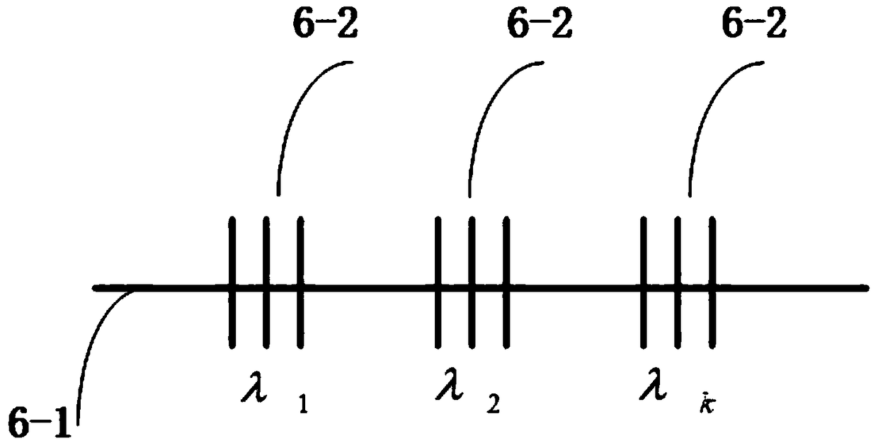
[0073] In a specific embodiment of the present invention, in combination with the present invention figure 1 The structure of an example given in , further elaborates the detection method of low reflection energy fiber gratings in a specific preferred implementation mode. This method can be applicable to in the optical cable system, in a specific embodiment, as figure 1 As shown, the system includes a broadband light source, an optical splitter, a high-speed optical switch 1, a circulator, an optical cable, a fiber grating string, a high-speed optical switch 2, a fiber grating demodulator, and a logic controller. The logic controller (11), broadband light source (1), fiber grating demodulator (10), high-speed optical switch one (2), high-speed optical switch two (8), attenuator one (3) and attenuation The broadband light source (1) is connected with the high-speed optical switch one (2); the high-speed optical switch one (2) is connected with the attenuator one (3); the atten...
Embodiment 3
[0084] In yet another specific embodiment, the present invention also provides a low reflection energy fiber grating detection method, which is applied to the detection of optical paths with fiber grating strings, and can also be applied to the above-mentioned embodiment 1 and embodiment 2 given in the detection system. The methods include:
[0085] Step 1, setting high-speed optical switch 1 and high-speed optical switch 2, through high-speed optical switch 1, the incident light is converted into detection light with a fixed pulse width, and once the high-speed optical switch is turned on, a fixed time T;
[0086] Step 2. The detection light is reflected at each fiber grating to form reflected light, and after controlling the high-speed optical switch 2 for a specific delay time, it is turned on for a fixed time T and receives the reflected light; During the time, half of the transmission distance of the incident light in the optical fiber is the distance of one detection; ...
PUM
 Abstract
Description
Claims
Application Information
 - R&D
- Intellectual Property
- Life Sciences
- Materials
- Tech Scout
- Unparalleled Data Quality
- Higher Quality Content
- 60% Fewer Hallucinations
Browse by: Latest US Patents, China's latest patents, Technical Efficacy Thesaurus, Application Domain, Technology Topic, Popular Technical Reports.
© 2025 PatSnap. All rights reserved.Legal|Privacy policy|Modern Slavery Act Transparency Statement|Sitemap|About US| Contact US: help@patsnap.com


