Turbo compressor fuel tank flue gas recovery device

A technology of turbo compressor and flue gas recovery, which is applied in the direction of combination device, transportation and packaging, dispersed particle filtration, etc., can solve the problems of easy oil leakage, poor oil and gas separation effect, etc. good filtering effect

Inactive Publication Date: 2019-02-22
DEYANG HONGYUAN ELECTROMECHANICAL ENG
View PDF1 Cites 0 Cited by
  • Summary
  • Abstract
  • Description
  • Claims
  • Application Information

AI Technical Summary

Problems solved by technology

[0008] In order to solve the above technical problems, the present invention proposes a turbine compressor oil tank flue gas recovery device, which can effectively solve the problems of poor oil-gas separation effect and easy oil leakage, and can better protect the environment

Method used


Image

  • Turbo compressor fuel tank flue gas recovery device

Examples


Embodiment 1

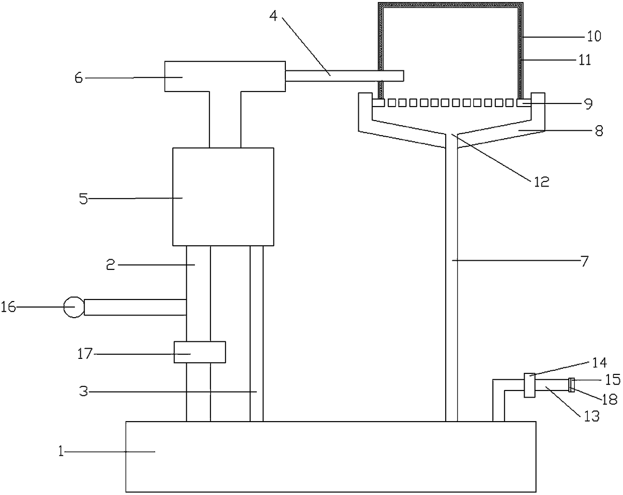
[0037] As the basic embodiment of the present invention, the present invention includes a turbine compressor oil tank flue gas recovery device, including an oil tank 1, a suction pipe 2, an oil return pipe 3, an exhaust pipe 4, an oil separator 5, a vacuum generator 6, Oil and gas filter device and second oil return pipe 7; the oil and gas filter device includes a support part 8, a leaky plate 9 and a filter, the support part 8 is in the shape of a groove, the leaky plate 9 is stuck in the groove, and the leaky plate 9 and the bottom of the support part 8 leave a gap; the filter is formed by connecting a plurality of side walls and a top, forming a cavity inside, and the bottom surface of the side wall is fixed to the upper surface of the drain plate 9; the side wall and the top It consists of two pieces of metal mesh 10 and a filter layer 11 filled between the two pieces of metal mesh 10; the cross section of the drain plate 9 is larger than the cross section of the filter; th...

Embodiment 2

[0039] As a preferred embodiment of the present invention, the present invention includes a turbine compressor oil tank flue gas recovery device, including oil tank 1, suction pipe 2, oil return pipe 3, exhaust pipe 4, oil separator 5, vacuum generator 6. Oil and gas filter device and second oil return pipe 7.

[0040] The oil-gas filtering device includes a support part 8, a leaky plate 9 and a filter, and the leaky plate 9 is provided with a number of holes; the support part 8 is square, with a groove in the middle, and the leaky plate 9 is square, and its size is the same as that of the groove. Matched, the interference fit is stuck in the groove, which is convenient for the leaky plate 9 and the support part 8 to be disassembled repeatedly, and is convenient to use; the said leaky plate 9 and the bottom of the groove leave a gap, which is convenient for the recovery of lubricating oil.

[0041] The filter is formed by connecting four side walls and a top, forming a cavity ...

Embodiment 3

[0046] As another preferred embodiment of the present invention, the present invention includes a turbine compressor oil tank flue gas recovery device, including oil tank 1, suction pipe 2, oil return pipe 3, exhaust pipe 4, oil separator 5, vacuum generating 6, an oil-gas filter device and a second oil return pipe 7; the oil-gas filter device includes a support part 8, a drain plate 9 and a filter, the support part 8 is in the shape of a groove, and the leak plate 9 is stuck in the groove, so There is a gap between the drain plate 9 and the bottom of the support portion 8; the filter is formed by connecting a plurality of side walls and a top, and a cavity is formed inside, and the bottom surface of the side wall is fixed to the upper surface of the drain plate 9; The wall and the top are respectively composed of two pieces of metal mesh 10 and a filter layer 11 filled between the two pieces of metal mesh 10; the cross section of the drain plate 9 is larger than the cross sect...


PUM

PropertyMeasurementUnit
pore sizeaaaaaaaaaa
pore sizeaaaaaaaaaa

Abstract

The invention relates to the field of flue gas recovery, in particular to a turbo compressor fuel tank flue gas recovery device comprising a fuel tank, an air suction pipe, a return oil pipe, an exhaust pipe, an oil separator, a vacuum generator, an oil and gas filter device and a second return oil pipe. The oil and gas filter device includes a supporting portion, a drain plate and a filter. The supporting portion is in a groove shape, the drain plate is clamped in the groove, and a gap is reserved between the drain plate and the bottom of the supporting portion, the filter is formed by connecting a plurality of side walls and one top, a cavity is formed internally, and the bottom surface of the side wall and the upper surface of the drain plate are fixed. The side walls and the top are each composed of two metal nets and a filter layer filling the two metal nets. The bottom of the supporting portion is further provided with an oil outlet, the oil outlet is connected with the fuel tankthrough the second return oil pipe, and the exhaust pipe extends into the cavity of the filter. Through the recovery device, the problems that an oil-gas separation effect is poor and oil leaks easily can be effectively solved, and the environment can be better protected.

Description

technical field [0001] The invention relates to the field of flue gas recovery, in particular to a turbo compressor oil tank flue gas recovery device. Background technique [0002] Due to the large power and high speed of the turbine compressor equipment, the temperature of the unit is high during operation, and lubricating oil is needed for lubrication and cooling, which produces oily smoke and oil mist to varying degrees, seriously polluting the atmosphere and the loss of oil products. At present, the flue gas from the oil tank of the turbine compressor in the industrial site is basically discharged in the factory building, such as in the auxiliary process of sponge titanium smelting, because the turbine compressor is in high frequency of use, in the production process, the oil tank of the turbine compressor There is a lot of smoke emission. Due to the small space of the plant, the entire plant has a large smoke concentration, which causes inconvenience to the operation of...

Claims


Application Information

Patent Timeline
Patent Type & Authority Applications(China)
IPC IPC(8): B01D46/00B01D46/24B01D50/00B01D46/48
CPCB01D46/2403B01D46/48B01D50/00B01D46/56B01D46/62
Inventor 王小龙赵成
Owner DEYANG HONGYUAN ELECTROMECHANICAL ENG
Why Eureka
Try Eureka