
Waste gas diluting high-temperature treatment equipment for chemical factory

A high-temperature treatment and waste gas technology, applied in gas treatment, auxiliary pretreatment, chemical/physical process, etc., can solve problems such as inability to purify, poor use of moisture, and lack of significant increase in humidity, so as to improve gasification speed, The effect of prolonging the service life and avoiding direct moisture and corrosion

Inactive Publication Date: 2019-02-22
宁波朗涌工贸有限公司
View PDF9 Cites 0 Cited by
  • Summary
  • Abstract
  • Description
  • Claims
  • Application Information

AI Technical Summary

Problems solved by technology

[0007] To sum up, the present invention provides high-temperature treatment equipment for diluted waste gas used in chemical plants. Through the improvement of structure and function, it solves the problem of single treatment method, poor use of moisture, slow dilution efficiency of gas, and continuous dilution. Purification, and does not have the function of greatly increasing the humidity

Method used


Image

  • Waste gas diluting high-temperature treatment equipment for chemical factory
  • Waste gas diluting high-temperature treatment equipment for chemical factory
  • Waste gas diluting high-temperature treatment equipment for chemical factory

Examples


Embodiment Construction

[0032] Embodiments of the present invention will be further described in detail below in conjunction with the accompanying drawings and examples. The following examples are used to illustrate the present invention, but should not be used to limit the scope of the present invention.

[0033] In the description of the present invention, unless otherwise stated, the meaning of "plurality" is two or more; the terms "upper", "lower", "left", "right", "inner", "outer" , "front end", "rear end", "head", "tail", etc. indicate the orientation or positional relationship based on the orientation or positional relationship shown in the drawings, and are only for the convenience of describing the present invention and simplifying the description, rather than Nothing indicating or implying that a referenced device or element must have a particular orientation, be constructed, and operate in a particular orientation should therefore not be construed as limiting the invention. In addition, t...


PUM


Abstract

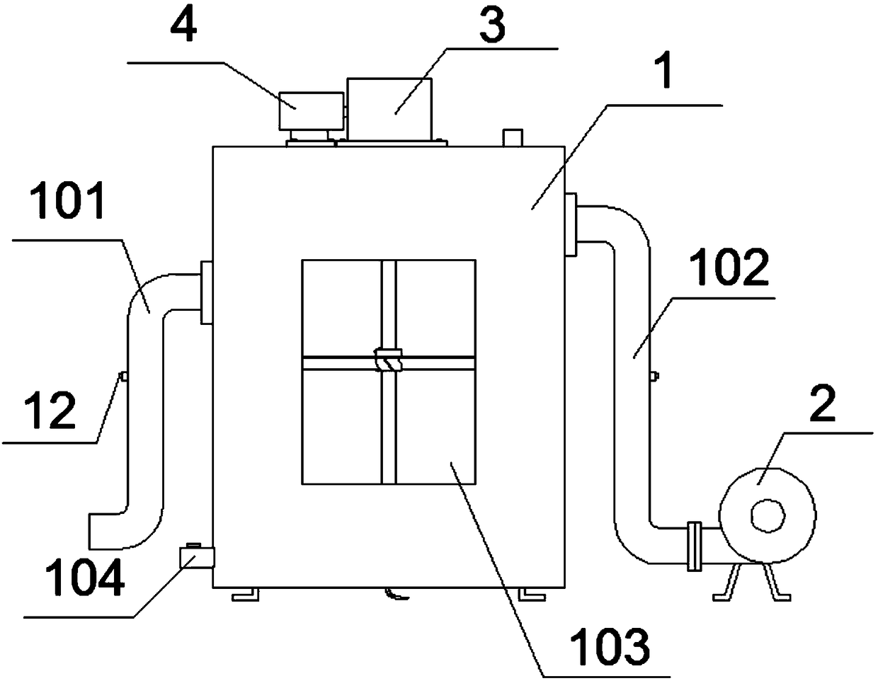
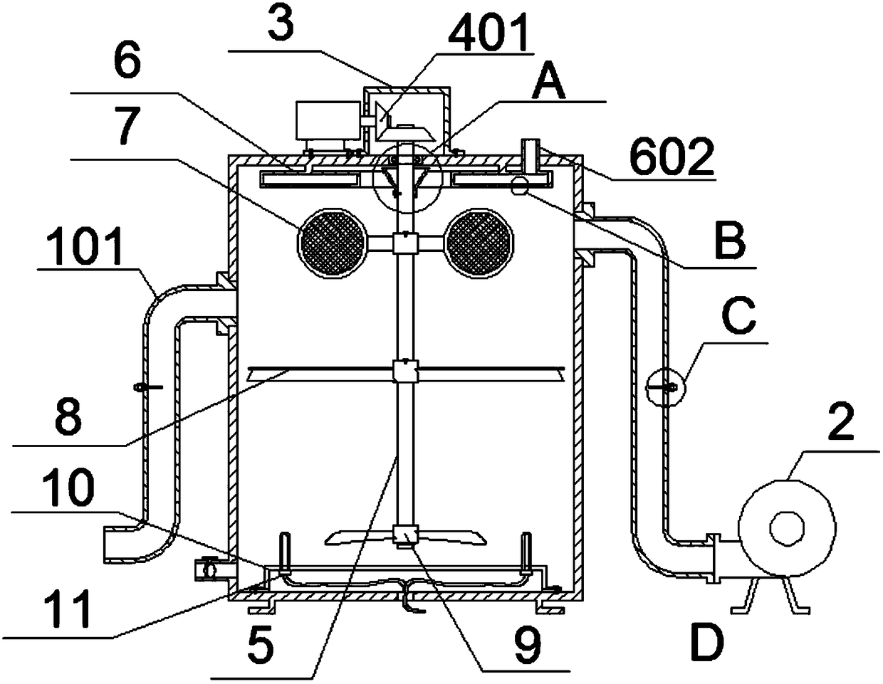
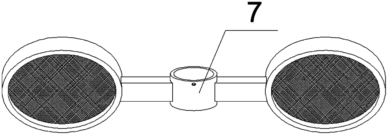
The invention provides waste gas diluting high-temperature treatment equipment for a chemical factory. The equipment comprises a tank, a gas inlet pipe, a gas outlet pipe, conical grooves, a water inlet pipe, a gas condensation assisting device, a gasification accelerating net, fan blades, a propeller, a seal cover, a heater, detectors, test paper grooves and jackscrews, wherein the gas inlet pipeand the gas outlet pipe are fixed on two sides of the tank by welding, and a fan is connected and fixed at one end of the gas outlet pipe in a sleeving manner; a square hole is formed in the front end of the tank, and observation glass is bonded and fixed in the square hole by a sealant; a drain port is integrally formed in one side of the bottom of the tank and is of a ball valve structure; by means of an annular water channel, water can be dispersed and sprayed into the tank, hydraulic pressure can be increased, water is sprayed in a water column manner, waste gas is diluted directly by spraying, moisture is increased, and waste gas dilution is realized.

Description

technical field [0001] The invention relates to the technical field of environmental protection, and more specifically relates to high-temperature treatment equipment for diluted waste gas used in chemical plants. Background technique [0002] Chemical waste gas refers to the toxic and harmful gas discharged from chemical plants in chemical production. Chemical waste gas often contains many types of pollutants, complex physical and chemical properties, and different toxicity. It seriously pollutes the environment and affects human health. The treatment equipment performs dilution treatment to protect the environment and purify the air by recovering or removing and reducing the harmful components of the exhaust gas. [0003] After retrieval, for example, the patent No. CN201620075237.0 discloses a two-way rotary spray industrial waste gas purification device, including a tower body; the tower body consists of a decomposition area, a first spray area, a second spray area and a...

Claims


Application Information

Patent Timeline
Patent Type & Authority Applications(China)
IPC IPC(8): B01F3/04C02F1/02B01D51/04B01D51/10
CPCB01D51/04B01D51/10C02F1/02B01D2258/02B01F23/21321B01F23/20
Inventor 鲍彦宗
Owner 宁波朗涌工贸有限公司
Learn More