Magnetic particle field flow separation device and method based on rotating magnetic field

A magnetic particle and field flow separation technology, applied in magnetic separation, chemical instruments and methods, solid separation, etc., can solve problems such as low precision and difficult implementation

Active Publication Date: 2021-03-02
DALIAN JIAOTONG UNIVERSITY
View PDF6 Cites 0 Cited by
  • Summary
  • Abstract
  • Description
  • Claims
  • Application Information

AI Technical Summary

Problems solved by technology

This rotating magnetic field changes the frequency of action of the magnetic field on the magnetic particles in the separation channel by adjusting the motor speed, and the accuracy is not high
To change the magnetic induction intensity in the separation channel, it is necessary to adjust the distance between the magnet and the separation channel, and it is difficult to ensure the parallelism between the rotation track of the magnet and the separation channel.

Method used


Image

  • Magnetic particle field flow separation device and method based on rotating magnetic field
  • Magnetic particle field flow separation device and method based on rotating magnetic field
  • Magnetic particle field flow separation device and method based on rotating magnetic field

Examples


Embodiment 1

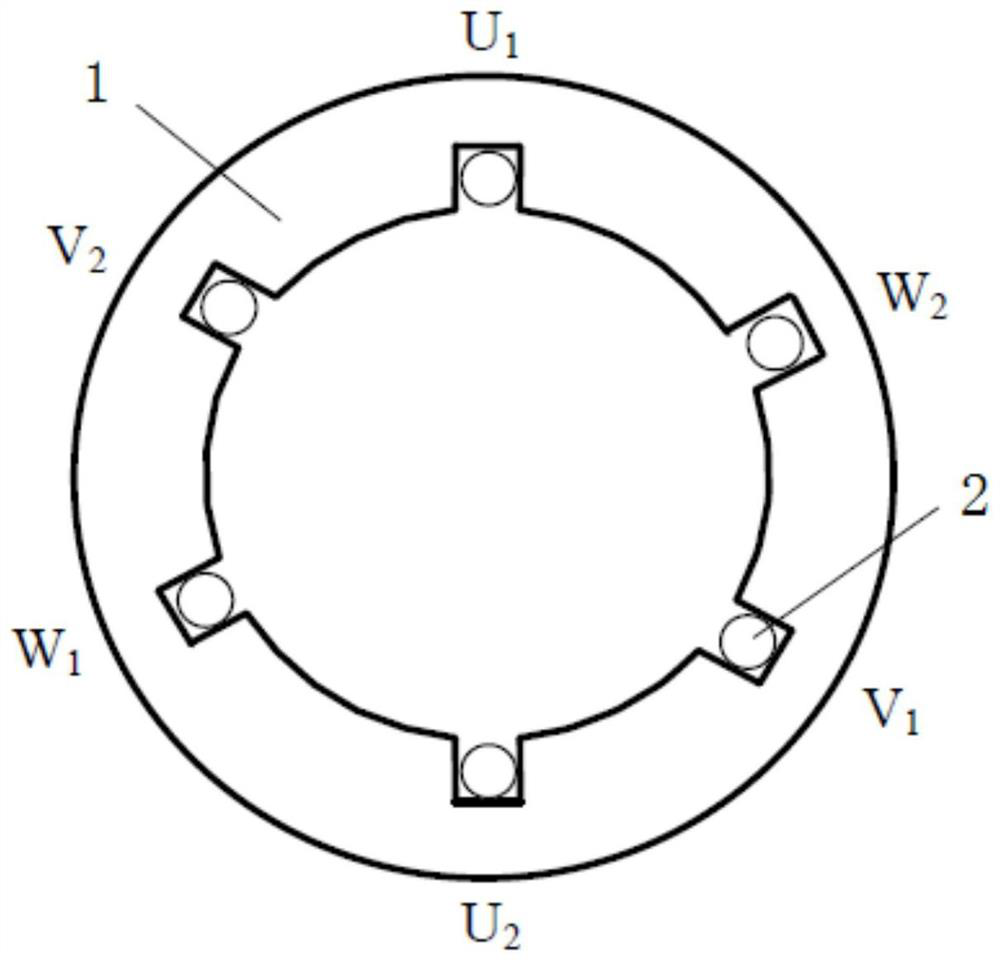
[0047] like Figure 1-Figure 6 As shown, a magnetic particle field flow separation device based on a rotating magnetic field, including a three-phase winding 2;

[0048] The three-phase winding 2 includes a first phase winding, a second phase winding and a third phase winding;

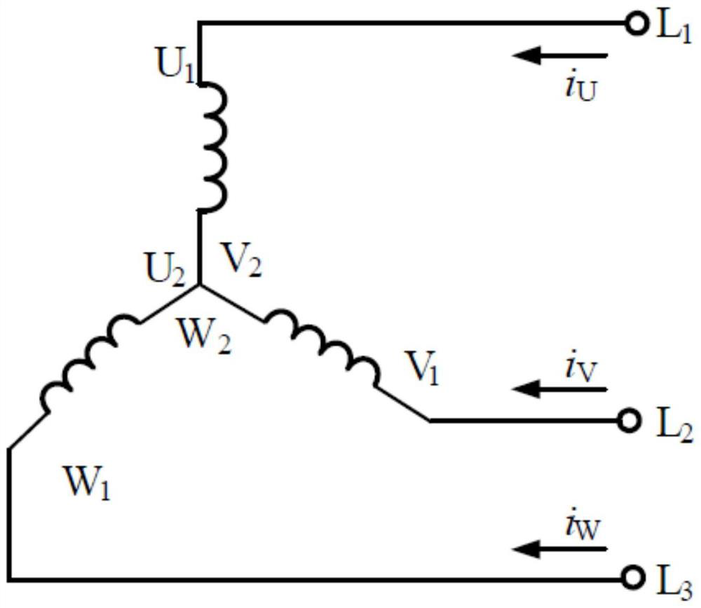
[0049] The first phase winding, the second phase winding and the third phase winding are star-connected and arranged on the base 1 axisymmetrically with the axis of the base 1;

[0050] The base 1 is a cast iron base;

[0051] The head end U of the first phase winding, the second phase winding and the third phase winding 1 , V 1 , W 1 Respectively with the output terminal L of the three-phase power supply 1 , L 2 , L 3 connected, the output current of the three-phase power supply is a symmetrical three-phase sinusoidal alternating current;

[0052] The base 1 is a hollow structure, and a separation channel is provided in the space surrounded by it;

[0053] The input end of the separation chan...

Embodiment 2

[0067] A method for magnetic particle field flow separation based on the magnetic particle field flow separation device described in embodiment 1, has the following steps:

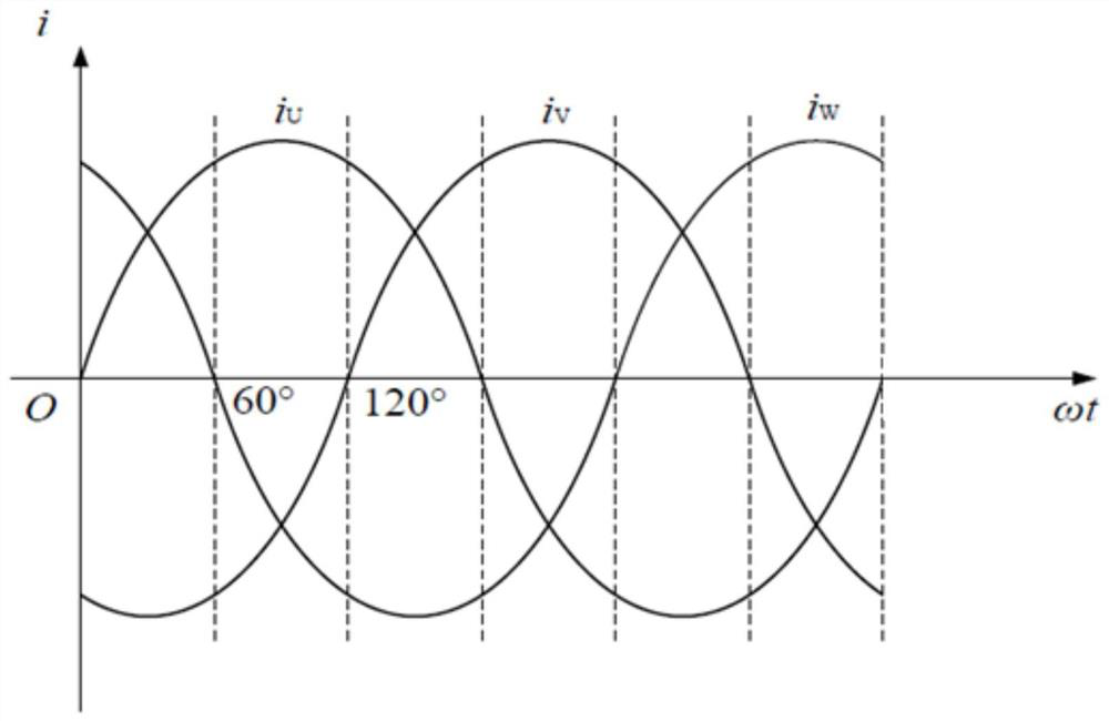
[0068] S1. The three-phase power supply inputs current i to the first phase winding, the second phase winding and the third phase winding respectively U i V i W , forming a rotating magnetic field in the space surrounded by the base 1, and adjusting the frequency of the rotating magnetic field and the voltage on the three-phase winding through the frequency converter 5;

[0069] S2. When the thickness of the plastic cylinder is constant, by changing the diameter of the inner wall and the diameter of the outer wall of the plastic cylinder, the radial position of the microtube is adjusted, and the magnetic induction intensity at the position of the separation channel is changed;

[0070] S3, the magnetic particles with different magnetic susceptibilities injected through the injection syringe 8 and the mob...


PUM

PropertyMeasurementUnit
particle diameteraaaaaaaaaa
diameteraaaaaaaaaa

Abstract

The invention discloses a magnetic particle field flow separation device and method based on a rotating magnetic field. The device includes a three-phase winding; the three-phase winding includes a first phase winding, a second phase winding and a third phase winding; the first phase winding , The second phase winding and the third phase winding are connected in a star shape and arranged on the base symmetrically with the axis of the base; The output terminals of the three-phase power supply are connected, and the output current of the three-phase power supply is a symmetrical three-phase sinusoidal alternating current; the base is a hollow structure, and a separation channel is provided in the space surrounded by it. The invention puts the separation channel into the inner cylindrical space formed by the three-phase winding and the base, and adjusts the magnitude and frequency of the three-phase voltage applied to the three-phase winding through a frequency converter. Control the frequency at which the magnetic particles are affected by the rotating magnetic field, change the magnetic induction intensity of the separation channel, and realize the field flow separation of magnetic particles with different particle sizes or the same size particles with different magnetic susceptibility.

Description

technical field [0001] The invention relates to the field of magnetic particle analysis and separation, in particular to a magnetic particle field flow separation device and method based on a rotating magnetic field. Background technique [0002] Magnetic particles have broad application prospects in the fields of magnetic drug manufacturing, magnetic resonance imaging, magnetic hyperthermia, and cell screening. The research on magnetic particles and microspheres has greatly promoted the development of biomedicine. [0003] In the application process of magnetic particles, it is required to have good monodispersity. The monodispersity of the magnetic particles refers to the uniformity of the particle diameter and the uniformity of the magnetic susceptibility. It is still difficult to obtain magnetic particles with good monodispersity by optimizing the process conditions during the preparation of magnetic particles, and further separation and screening of the prepared magnet...

Claims


Application Information

Patent Timeline
Patent Type & Authority Patents(China)
IPC IPC(8): B03C1/32
CPCB03C1/32
Inventor 邵力耕冯志华
Owner DALIAN JIAOTONG UNIVERSITY
Why Eureka
Try Eureka