Hydrogen removal device for marine electrolytic ballast water treatment system

An electrolytic compression and management system technology, which is applied in the field of hydrogen treatment devices for flammable and explosive by-products, can solve the problems of difficult installation, long hydrogen exhaust pipelines, and high equipment costs, and achieve improved efficiency, low cost, and simple equipment Effect

Pending Publication Date: 2019-02-22
JIUJIANG PRECISION MEASURING TECH RES INST
View PDF11 Cites 3 Cited by
  • Summary
  • Abstract
  • Description
  • Claims
  • Application Information

AI Technical Summary

Problems solved by technology

[0007] The purpose of the present invention is to provide a treatment device for by-product hydrogen in the process of ship electrolysis ballast water treatment, so as to solve the problem in the prior art that the separated hydrogen needs

Method used


Image

  • Hydrogen removal device for marine electrolytic ballast water treatment system

Examples


Embodiment Construction

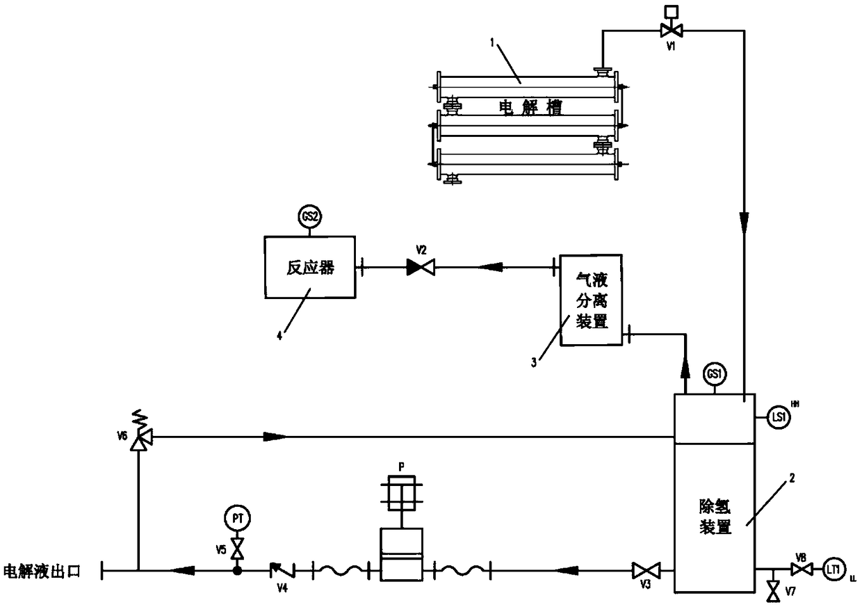
[0020] see figure 1 , The present invention is a treatment device for by-product hydrogen in the treatment process of ship electrolysis ballast water management system, which is characterized in that it includes an electrolytic cell 1, a hydrogen removal device 2, a gas-liquid separation device 3, and a reactor 4 connected in sequence. The outlet of the existing seawater electrolysis device 1 discharge (containing hydrogen) electrolyte is connected with the inlet of the dehydrogenation device 2, and the upper gas outlet of the dehydrogenation device 2 is connected with the inlet of the gas-liquid separation device 3, and the gas-liquid separation device 3 The gas outlet of is connected with the inlet of reactor 4 through a check valve V2. The reactor is equipped with a resistance heating device, a temperature control device, and a temperature real-time monitoring sensor. In the figure, the automatic valve V1 sequentially connected to the seawater introduction pipeline is a su...


PUM


Abstract

The invention discloses a hydrogen removal device for a marine electrolytic ballast water treatment system. The operating method comprises the following steps: performing gas-liquid separation on electrolyte discharged by a seawater electrolysis unit in a gas-liquid separation unit; drying the separated hydrogen by a dryer; and finally, feeding the dried mixed gas into a CuO reactor. The hydrogenremoval device disclosed by the invention has the technical effects that the electrolyte produced by electrolysis is first subjected to gas-liquid separation, dried and introduced into the CuO reactorfor carrying out a redox reaction when the electrolysis unit for the ballast water treatment system is operated, and reduced Cu and water can be produced, so that the aim of removing the hydrogen isachieved. The reduced Cu and H2O are easily oxidized to produce CuO, so that the recycling aim is achieved. The by-product hydrogen is effectively treated, the marine safety is ensured, the equipmentis simple, the cost is low, a long hydrogen removal pipeline does not need to be installed, and leakage risk is reduced.

Description

technical field [0001] The invention relates to a processing device for treating inflammable and explosive by-product hydrogen that endangers the normal navigation of the ship during the operation of the ship's electrolytic ballast water processing device. Background technique [0002] IMO adopted the "International Convention on the Control and Management of Ships' Ballast Water and Sediments" in 2004. The "Convention" stipulates: (1) There are less than 10 living organisms with a minimum size ≥ 50 μm per m3 of discharged ballast water; (2) ) less than 10 viable organisms with a minimum size of <50μm but >10μm per ml in discharged ballast water; (3) toxic Vibrio cholerae (O1 and O139) must be less than 1cfu per 100ml of ballast water; (4) per 100ml Escherichia coli in ballast water must be less than 250cfu; (5) Enterococcus per 100ml of ballast water must be less than 100cfu. The convention will enter into force within 12 months of being ratified by the 30 member sta...

Claims


Application Information

Patent Timeline
IPC IPC(8): C02F1/461B63J4/00C25B1/04B01D53/81
CPCB01D53/81C25B1/04B63J4/002C02F1/46104C02F2201/46105C02F2103/008C02F2303/10C02F2303/14B01D2251/602B01D2257/108Y02E60/36
Inventor 李志强周仕华马骥李晓晓付小敏
Owner JIUJIANG PRECISION MEASURING TECH RES INST
Why Eureka
Try Eureka