
Engineering measurement and pay-off device

A pay-off device and engineering surveying technology, which is applied to measuring devices, surveying instruments, surveying and navigation, etc., can solve the problems of reduced service life of the pay-off device, poor rotation of the wire wheel, pollution of the wire wheel toner, etc., and achieve improvement Service life, wear reduction, wear reduction effect

Active Publication Date: 2020-12-04
广东粤路勘察设计有限公司
View PDF8 Cites 0 Cited by
  • Summary
  • Abstract
  • Description
  • Claims
  • Application Information

AI Technical Summary

Problems solved by technology

[0004] However, because the ink thread absorbs a large amount of toner, after the ink thread is used up, the toner will be taken to the wire wheel during the winding process, so that the wire wheel is polluted by toner, and in severe cases, it may also be caused by infiltration into the wire wheel rotation shaft. Too much toner in the gap causes the wire wheel to rotate poorly or even get stuck, which reduces the service life of the pay-off device, so there is still room for improvement

Method used

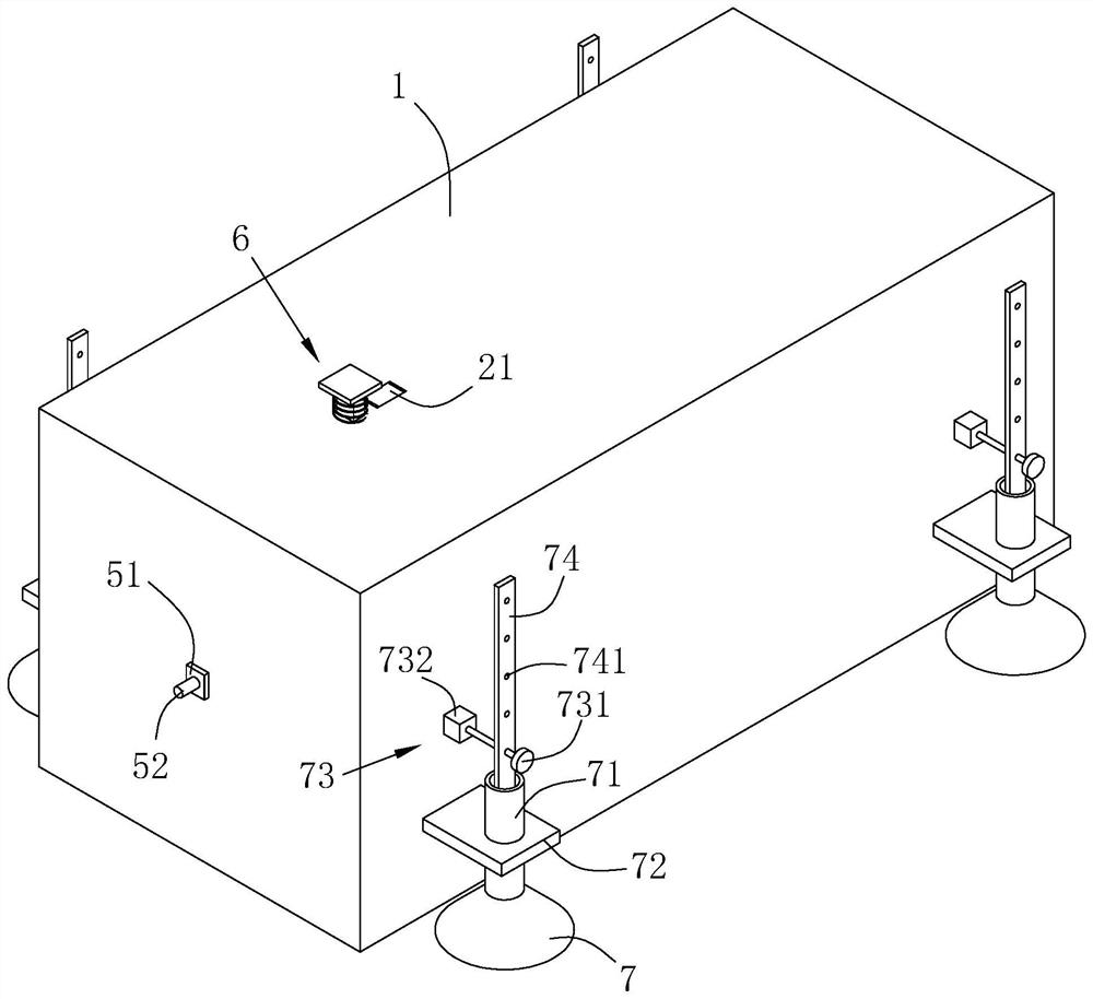
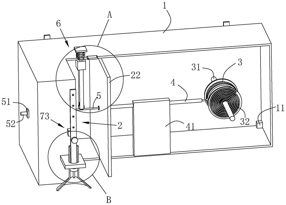
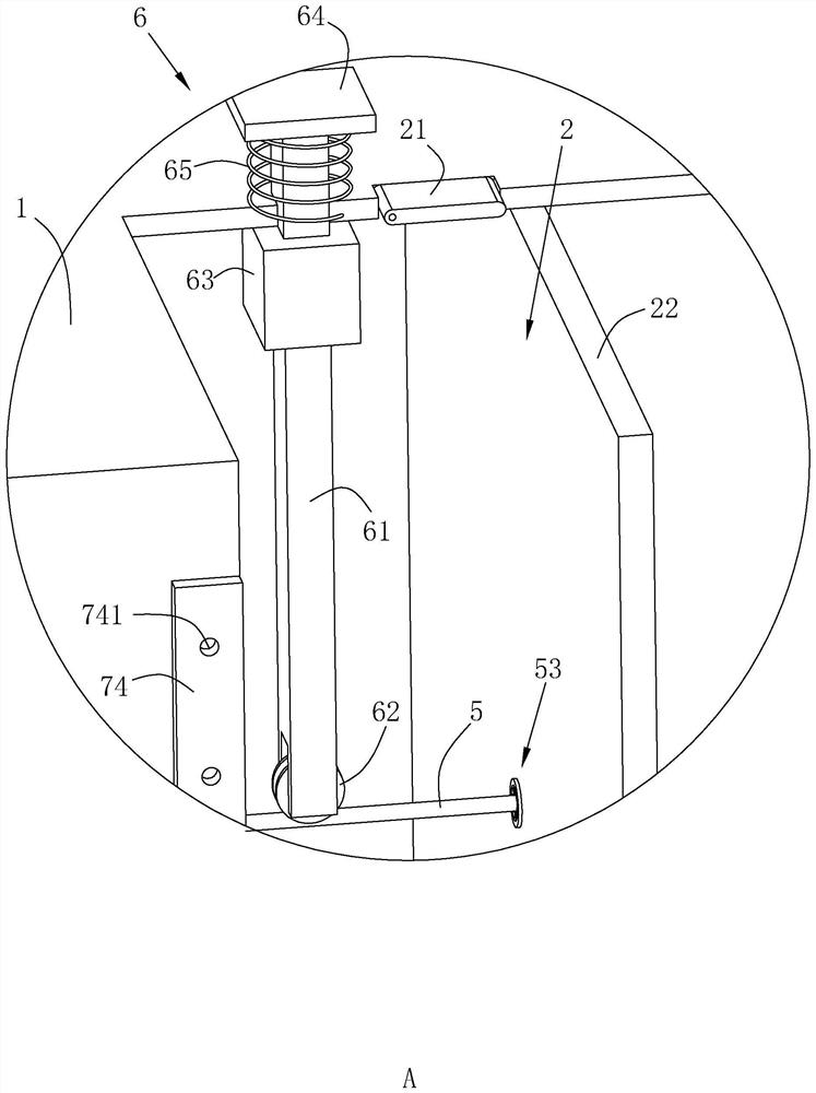

Image

  • Engineering measurement and pay-off device
  • Engineering measurement and pay-off device
  • Engineering measurement and pay-off device

Examples


preparation example Construction

[0066] The preparation method of ink line 5 is as follows:

[0067] Add natural rubber to the open mill, roll speed 30r / min, roll distance 5mm, and masticate for 30s; add silica and silane coupling agent, roll speed 30r / min, roll distance 4mm, and knead for 60s; add oil, hard Sodium fatty acid and ceramic powder, roll speed 45r / min, roll distance 3.5mm, knead for 45s; add paraffin, roll speed 45r / min, roll distance 3mm, knead for 45s, add sulfur and accelerator, roll speed 45r / min , the roller distance is 2mm, the mixing is 30s, the roller speed is 60r / min, the roller distance is 1.5mm, the mixing is 45s, and the rubber is discharged to form a mixed rubber.

[0068] Put the mixed rubber into the screw extruder to extrude the unvulcanized ink line 5, then put the unvulcanized ink line 5 into the oven to heat and cross-link to form the ink line 5, the vulcanization temperature is 150°C, the nitrogen pressure is 10MPa, and the vulcanization time is 30min.

[0069] Friction tube...

Embodiment 2

[0090] Ink line 5 includes the following components in parts by mass:

[0091] 100 parts of natural rubber; 12 parts of oil; 23 parts of paraffin; 45 parts of white carbon black; 8 parts of sodium stearate; 4 parts of ceramic powder; 4 parts of silane coupling agent; 2 parts of sulfur; 1 part of accelerator.

[0092] Friction tube 4 includes the following components in parts by mass:

[0093] 100 parts of polytetrafluoroethylene; 4 parts of silane coupling agent; 18 parts of corundum.

Embodiment 3

[0095] Ink line 5 includes the following components in parts by mass:

[0096] 100 parts of natural rubber; 15 parts of oil; 25 parts of paraffin; 50 parts of white carbon black; 10 parts of sodium stearate; 5 parts of ceramic powder; 5 parts of silane coupling agent; 3 parts of sulfur; 2 parts of accelerator.

[0097] Friction tube 4 includes the following components in parts by mass:

[0098] 100 parts of polytetrafluoroethylene; 5 parts of silane coupling agent; 20 parts of corundum.


PUM


Abstract

The invention relates to the technical field of engineering surveying and provides an engineering surveying paying-off device to solve the problem that the service life of the paying-off device is shortened. The technical scheme is as follows: the engineering surveying paying-off device comprises a mounting shell, an ink cabin and a wire wheel are mounted in the mounting shell, an ink wire winds the wire wheel, an ink moistening part for driving the ink wire to enter the ink cabin for ink moistening is arranged in the mounting shell, a wire outlet hole through which the ink wire stretches outof the mounting shell is formed in the mounting shell, a friction pipe is fixed in the mounting shell, the ink wire is inserted into the friction pipe and slides along the friction pipe, the ink wireis made from rubber and is smooth in surface, the friction pipe is made from a plastic and is smooth in inner surface, the inner diameter of the friction pipe is consistent to the outer diameter of the ink wire, and brushing hairs for cleaning the ink wire are arranged in the ink cabin. The ink wire and the friction pipe have friction to generate static electricity to adsorb ink powder, the ink wire is smooth in surface, and when the ink wire is recovered, ink powder on the ink wire can be cleaned thoroughly easily by the brushing hairs, the condition that the ink powder is brought to the wirewheel to erode a rotating wheel of the wire wheel is avoided, and the service life of the paying-off device is prolonged.

Description

technical field [0001] The invention relates to the technical field of engineering survey, more specifically, it relates to an engineering survey pay-off device. Background technique [0002] The ink fountain is composed of four parts: the ink chamber, the wire wheel, the ink thread (including the wire cone), and the ink stick. It is a very common tool in the traditional Chinese woodworking industry. Ink fountains are commonly used for things like surveying and house building. [0003] Since the ink line needs to be moistened, the toner can be bounced to the plane to be drawn by the spring line, and the ink line is usually made of cotton thread to absorb a large amount of toner by using the cotton thread's own porous structure, thereby ensuring the clarity of the line mark. [0004] However, because the ink thread absorbs a large amount of toner, after the ink thread is used up, the toner will be taken to the wire wheel during the winding process, so that the wire wheel is ...

Claims


Application Information

Patent Timeline
Patent Type & Authority Patents(China)
IPC IPC(8): G01C15/00
CPCG01C15/00
Inventor 赖毅
Owner 广东粤路勘察设计有限公司
Learn More