A double-pulse test circuit and method for a flying capacitor three-level dcdc power component

A technology of flying capacitors and power components, which is applied in the pulse test circuit field of flying capacitor three-level DCDC power components, can solve the problem that the double pulse test method cannot be directly applied to flying capacitor three-level power components, and achieve Effectiveness of reliable and valid test methods

Active Publication Date: 2021-02-05
NARI TECH CO LTD +1
View PDF8 Cites 0 Cited by
  • Summary
  • Abstract
  • Description
  • Claims
  • Application Information

AI Technical Summary

Problems solved by technology

However, the traditional double-pulse test method for two-level DCDC power components cannot be directly applied to flying-capacitor three-level power components. Therefore, it is of great practical significance to study the double-pulse test method for flying-capacitor three-level DCDC power components.

Method used


Image

  • A double-pulse test circuit and method for a flying capacitor three-level dcdc power component
  • A double-pulse test circuit and method for a flying capacitor three-level dcdc power component
  • A double-pulse test circuit and method for a flying capacitor three-level dcdc power component

Examples


Embodiment 1

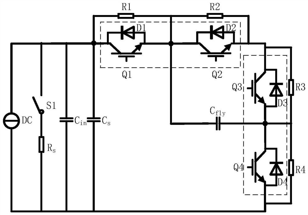
[0053] refer to figure 1 As shown, the double-pulse test circuit of the flying capacitor three-level DC / DC power component of this embodiment includes a three-level power module, an adjustable DC source DC, a discharge branch and a freewheeling inductance L;

[0054] The three-level power module includes the flying capacitor C fly , DC support capacitor C in , Snubber capacitance C s and a switch conversion circuit; the switch conversion circuit includes a first IGBT switch tube Q1, a second IGBT switch tube Q2, a third IGBT switch tube Q3, and a fourth IGBT switch tube Q4 connected in series in the same direction; the emitters of each IGBT and The freewheeling diodes D1-D4 are respectively reversely connected to the collectors; one end of the flying capacitor C is connected between the first IGBT emitter and the second IGBT collector, and the other end is connected between the third IGBT emitter and the fourth IGBT between IGBT collectors;

[0055] The first IGBT, the sec...

Embodiment 2

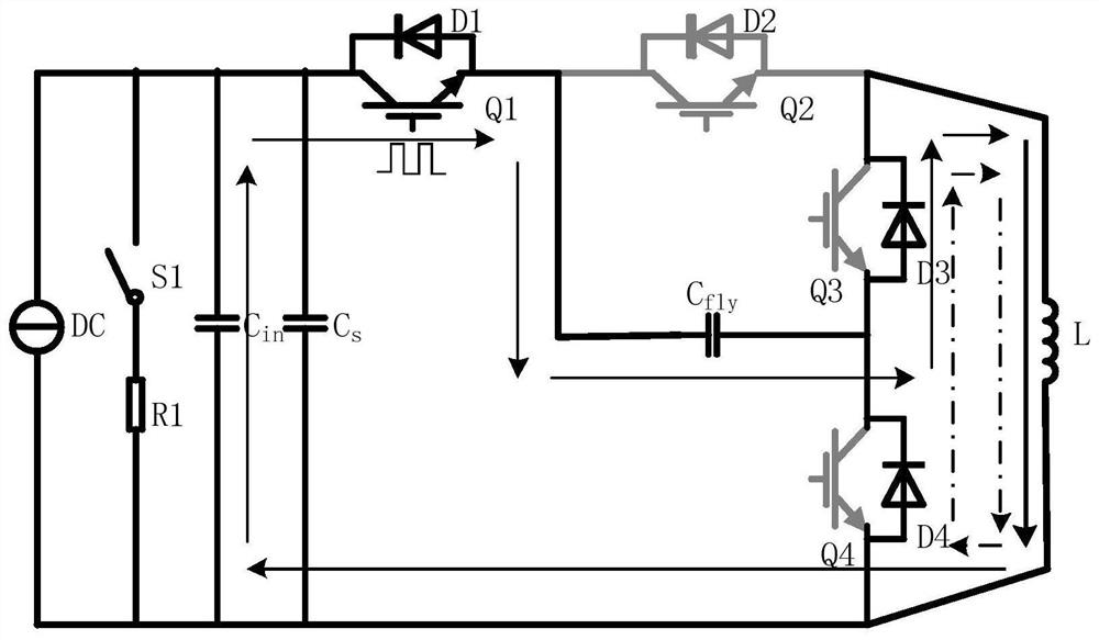
[0066] Based on the test circuit of Embodiment 1, this embodiment is a test method for a double-pulse test circuit of a flying capacitor three-level DC / DC power component, including:

[0067] Adjust the adjustable DC source DC to charge the support capacitor to the rated voltage V DC , and then charge the flying capacitor to V through the equalizing resistors R1-R4 DC / 2;

[0068] Disconnect the adjustable DC source DC to stop charging;

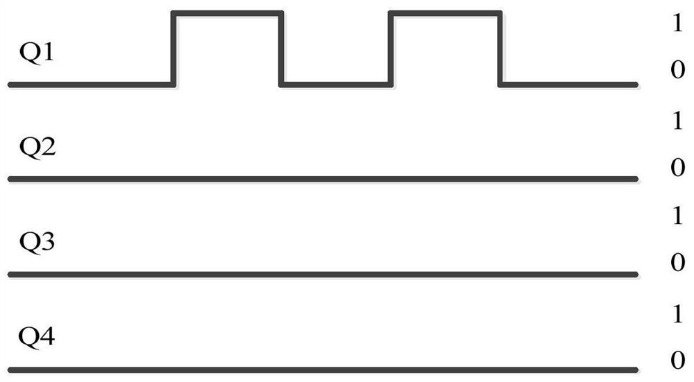
[0069] Determine the switching transformation form of the three-level power module and the corresponding test object IGBT switch tube;

[0070] According to the switch conversion form, control the IGBT switch tubes other than the test object IGBT switch tube to turn off or normally open;

[0071] Apply double pulses to the IGBT switch tube of the test object;

[0072] Measure the gate-emitter voltage V of the IGBT switch tube of the test object during the application of the double pulse GE , collector-emitter voltage V CE , and the reve...


PUM


Abstract

The invention discloses a pulse test circuit and method for a flying capacitor three-level DCDC power component. The test circuit includes a three-level power module, an adjustable DC source, a discharge branch and a freewheeling inductor; the three-level power module includes The supporting capacitor, the flying capacitor, the absorbing capacitor and the first to fourth IGBTs connected in series in sequence; each IGBT is connected in parallel with a voltage equalizing resistor and a reverse freewheeling diode; the adjustable DC source, the discharge branch, and the supporting capacitor, The absorbing capacitor and the switch conversion circuit are connected in parallel; when the three-level power module works in the Buck mode, the freewheeling inductor is connected in parallel between the third IGBT and the fourth IGBT; when the three-level power module works in the Boost mode, continued The flow inductor is connected in parallel between the first IGBT and the second IGBT in series. The present invention makes each IGBT undergo the turn-on-off-turn-on-off process by controlling different switching modes, can examine the ability of power components to withstand overcurrent and turn-on and turn-off characteristics, and analyze the stray inductance of the commutation circuit and the resulting overvoltage conditions and improve system design.

Description

technical field [0001] The invention relates to the technical field of power electronics applications, in particular to a pulse test circuit and method for a flying capacitor three-level DCDC power component. Background technique [0002] With the development of power electronics technology, DCDC power converters have been widely used in fields including new energy electric vehicle charging and energy storage tram charging systems, and the capacity and voltage level of charging systems are also getting higher and higher. Compared with the traditional two-level converter, the flying capacitor type three-level DCDC converter has the characteristics of high efficiency and high switching frequency. Higher power levels and switching frequencies also mean higher rates of voltage and current change, and the voltage spikes superimposed on the stray inductance in the commutation circuit are added to both ends of the IGBT, which may cause overvoltage damage to the device. Therefore, ...

Claims


Application Information

Patent Timeline
Patent Type & Authority Patents(China)
IPC IPC(8): G01R31/00G01R31/327
CPCG01R31/00G01R31/327
Inventor 雷磊郭巍吴维宁石磊田炜孙祖勇陶正华张文波
Owner NARI TECH CO LTD
Why Eureka
Try Eureka