All-solid-state planar array three-dimensional imaging laser radar system

A laser radar and three-dimensional imaging technology, applied in radio wave measurement systems, electromagnetic wave re-radiation, utilization of re-radiation, etc., can solve the problems of poor system consistency, long production cycle, complex optical path debugging and assembly process, etc.

Active Publication Date: 2019-02-22
BEIJING HUA KEBO BOCHUANG TECH
View PDF7 Cites 29 Cited by
  • Summary
  • Abstract
  • Description
  • Claims
  • Application Information

AI Technical Summary

Problems solved by technology

[0007] Whether it is a point-scanning lidar through a two-dimensional mechanical galvanometer or a multi-line mechanical scanning radar, there are many optical components. In order to ensure measurement accuracy, the requirements for the assembly process of optical components and mechanical galvanometers are relatively high. The debugging and assembly process is relatively complicated, and the consistency of the system is poor, which also leads to a long production cycle and high cost of the product, which is not conducive to mass production and civilian market promotion
[0008] 2) The ranging accuracy is low
The timing circuit of this technology route adopts the circuit design principle of multi-level separation devices. At the same time, due to the limitation of the timing accuracy of the TDC chip itself, the ranging accuracy of the entire system cannot be improved, especially at short distances (within tens of meters). It is very large and cannot meet the measurement requirements of close-ra

Method used


Image

  • All-solid-state planar array three-dimensional imaging laser radar system
  • All-solid-state planar array three-dimensional imaging laser radar system
  • All-solid-state planar array three-dimensional imaging laser radar system

Examples


Embodiment Construction

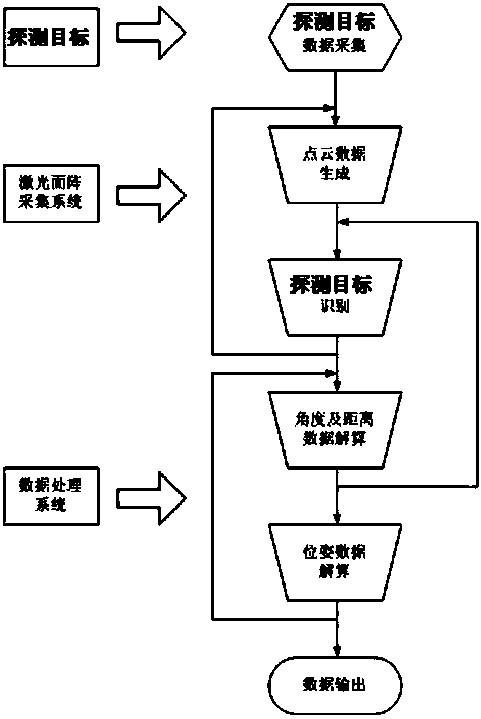
[0044] In order to meet the precision ranging requirements of spacecraft and cooperative targets, this embodiment designs a high-precision laser ranging radar system to complete the measurement of high-precision distance information, angle information and lateral position information for spacecraft rendezvous and docking, and realize spacecraft rendezvous Precise positioning of docking.

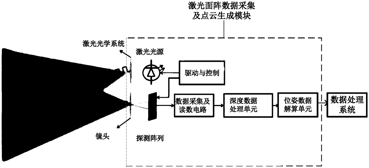
[0045] see Figure 1-2 , the all-solid-state area array three-dimensional imaging laser radar system of this embodiment includes: detection target, the design of the detection target needs to take into account both the far field and the near field, and the detection target is an important part of the laser radar measurement system in this embodiment, usually The reflector array composed of multiple corner cube prisms is installed on the docking surface of the target aircraft, so that the laser signal emitted by the laser radar measurement system on the tracking spacecraft returns to the origi...


PUM


Abstract

The invention provides an all-solid-state planar array three-dimensional imaging laser radar system, which comprises a detection target, a laser planar array data acquisition and point cloud generating module, and a data processing system, wherein the detection target is installed on a butting surface of a all-solid-state planar array three-dimensional imaging laser radar, so that a pulse laser signal transmitted by means of the laser radar for tracking the detection target returns in the original path, a reception and detection system of the laser radar completes the searching and capture ofthe detection target, acquires relative distance and position measurement parameters of the detection target in real time and acquires a plurality of feature points of the detection target in a laserirradiation range of the detection target and the laser radar, and the feature points are set in an optical field of view region with a fixed divergence angle; the laser planar array data acquisitionand point cloud generating module completes the measurement of the detection target and the depth data generation of the feature points, and transmits the depth data to the data processing system; andthe data processing system calculates azimuth information according to the depth data of each feature point and pixel positions in the field of view region, calculates angle and distance data and calculates attitude data of the detection target.

Description

technical field [0001] The invention relates to laser radar technology, and in particular to an all-solid-state array three-dimensional imaging laser radar system. Background technique [0002] Lidar is classified into mechanical lidar and solid-state lidar according to the presence or absence of mechanical rotating parts. Mechanical lidar has rotating parts that control the angle of laser emission, while solid-state lidar relies on electronic components to control the angle of laser emission without mechanical rotating parts. The traditional laser radar is mainly a mechanical scanning radar, which is characterized by low scanning frame frequency, slow speed, large size, high cost, and long distance. It is mainly used in military and national geographic information remote sensing detection, resource survey, earthquake prevention and disaster reduction, and national key Construction projects and other aspects provide extremely important raw materials for national economy, so...

Claims


Application Information

Patent Timeline
IPC IPC(8): G01S17/89G01S7/481
CPCG01S7/481G01S17/89
Inventor 孙礼朋陈永然
Owner BEIJING HUA KEBO BOCHUANG TECH
Why Eureka
Try Eureka