Anti-corrosion coating brush printing device for electronic chip

A technology for anti-corrosion coatings and electronic chips, applied in coatings, devices for coating liquid on surfaces, etc., can solve the problems of poor brushing thickness, uneven brushing, low efficiency, etc., and achieve better brushing effect Effect

Inactive Publication Date: 2019-02-26
郑州莱兹电子科技有限公司
View PDF6 Cites 9 Cited by
  • Summary
  • Abstract
  • Description
  • Claims
  • Application Information

AI Technical Summary

Problems solved by technology

[0004] Existing electronic chip coatings are often manually brushed, and some chips are sprayed by e

Method used


Image

  • Anti-corrosion coating brush printing device for electronic chip
  • Anti-corrosion coating brush printing device for electronic chip
  • Anti-corrosion coating brush printing device for electronic chip

Examples


Embodiment 1

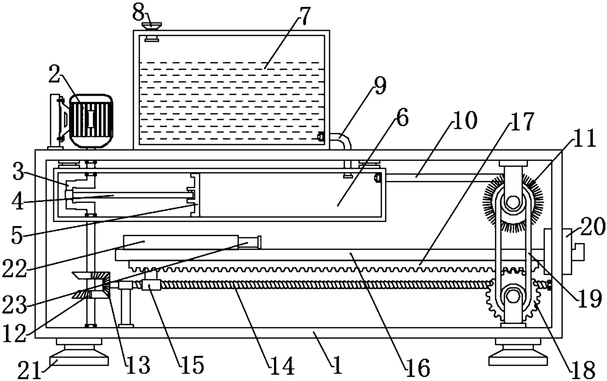
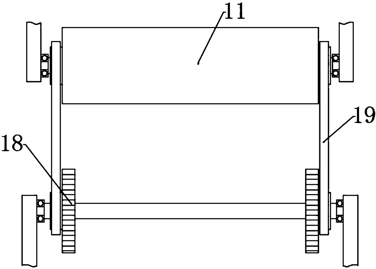
[0022] see Figure 1~3 , in an embodiment of the present invention, an electronic chip anti-corrosion coating printing device, including a device body 1, a crankshaft 3, a spray box 6, a brush roller 11, a workbench 16 and a gear 18; the upper left side of the device body 1 is set There is a drive motor 2, the drive motor 2 is fixedly connected to the motor base, the motor base is fixedly connected to the vertical support plate by bolts, the vertical support plate is fixedly connected to the device body 1, and the lower part of the drive motor 2 is connected to the crankshaft 3 in rotation, and the crankshaft 3 passes through the device The upper edge of the body 1 is rotationally connected with the bearing, the driving motor 2 is connected to the power supply and the switch by wires, and the switch is pressed to make the driving motor 2 energized to drive the crankshaft 3 to rotate; the upper part of the device body 1 is fixedly connected with the spray box 6 and the crankshaf...

Embodiment 2

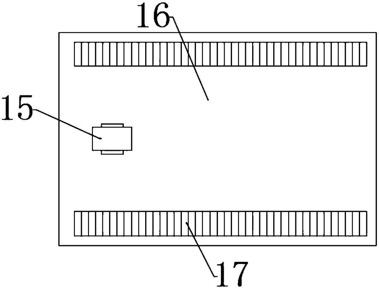
[0025] In order to make the technical solution of the present application more complete and detailed, some supplementary explanations are made on the basis of the above-mentioned embodiment 1, so that the disclosure of the technical means adopted in the present application is more sufficient. Specifically, the technical characteristics of the added part are , the top left end of the workbench 16 is fixedly connected to the cylinder 22, the inside of the cylinder 22 is sealed and slidably connected to the telescopic rod 23, the two sides of the lower end of the device body 1 are respectively fixedly connected to the legs 21, and the upper right end of the workbench 16 is provided with a raised bump. The chips to be processed are placed on the workbench 16 and clamped by the bumps cooperating with the telescopic rods 23 , so as to achieve the functions of stabilization and clamping.

[0026] The working principle of the present invention is: press the switch to make the drive mot...


PUM


Abstract

The invention discloses an anti-corrosion coating brush printing device for an electronic chip, the anti-corrosion coating brush printing device comprises a device body, a crankshaft, a spraying box,a brush roller, a workbench and a gear; wherein a driving motor is arranged on the left side of the upper part of the device body, the driving motor is fixedly connected with a motor base, the lower portion of the driving motor is rotationally connected with the crankshaft, the crankshaft penetrates through the upper edge of the device body and is rotationally connected with a bearing, the spraying box is fixedly connected to the inner part of the upper portion of the device body, the crankshaft penetrates through the spraying box and is rotationally connected with the bearing, the bent part of the crankshaft is sleeved with one end of a connecting rod, the other end of the connecting rod is rotationally connected with a plunger, and the edge of the plunger is slidably connected with the inner wall of the spraying box in a sealing manner. The device achieves an automatic feeding function by use of the crankshaft to drive the plunger to move left and right, meanwhile, a semi-conical gear and a bevel gear drive a screw rod to do reciprocating forward and reverse rotation so as to drive a workbench to move left and right in a reciprocating manner, the gear and the brush roller are driven to rotate while the workbench moves left and right in the reciprocating manner, and the rotating brush roller is matched with the workbench which moves left and right in the reciprocating manner to carry out omni-directional brush coating on the chip.

Description

technical field [0001] The invention relates to an electronic equipment processing device, in particular to an electronic chip anti-corrosion coating printing device. Background technique [0002] Electronic chips, also known as microcircuits, microchips, and integrated circuits, refer to silicon chips containing integrated circuits, which are small in size and are often part of computers or other electronic equipment. If the central processing unit CPU is compared to the heart of the entire computer system, then the chipset on the motherboard is the trunk of the entire body. For the motherboard, the chipset almost determines the function of the motherboard, which in turn affects the performance of the entire computer system. The chipset is the soul of the motherboard. [0003] Since electronic chips are often embedded in circuit boards and are in high-temperature and high-voltage circuits all year round, it is necessary to brush a layer of insulating and anti-corrosion coa...

Claims


Application Information

Patent Timeline
IPC IPC(8): B05C1/08B05C11/10B05C13/02
Inventor 张焕
Owner 郑州莱兹电子科技有限公司
Why Eureka
Try Eureka