Heat treatment method for middle ring of synchronizer and middle ring structure

A heat treatment method and intermediate ring technology, which are applied in heat treatment furnaces, heat treatment equipment, couplings, etc., can solve the problems of wear of synchronizer intermediate rings and synchronizing rings, unstable oil volume, and prone to broken claws. Wear, improved stability, good lubrication effect

Pending Publication Date: 2019-02-26
江苏持华科技有限公司
View PDF9 Cites 0 Cited by
  • Summary
  • Abstract
  • Description
  • Claims
  • Application Information

AI Technical Summary

Problems solved by technology

[0002] The synchronizer is a very important part in the car transmission system, which makes the car's speed change process very smooth and reliable, and the intermediate ring is a very important part of the synchronizer. The intermediate ring includes a conical cone ring and a ring connected to the ring Several claws on the gear, the claws can cooperate with the claw holes on the gear to be combined, and the intermediate ring is connected to the gear to be combined to rotate synchronously, and the outer cone surface is in contact with the inner cone surface of the synchronous ring, and with the contact tightness The friction between the two is constantly increasing, which drives the synchronous ring and the intermediate ring to rotate synchronously, and finally realizes the synchronous rotation of the combined gear and the synchronous ring. However, during the shifting operation, the traditional synchronizer The movement of the intermediate ring has a certain impact, and it is easy to break the claws during actual use. However, most foreign intermediate ring products are made of carburized steel. In the actual processing process, carburizing and quenching processes are required to improve the durability of the product. price
[0003] During the working process of the existing synchronizer, the friction cone surface of the synchronizer intermediate ring is lubricated by the splash lubrication of the driven gear of the gearbox. The amount of oil is unstable and difficult to control. If the amount of splashed oil is small, it may cause synchronization Early wear and even ablation of intermediate ring and synchronous ring

Method used


Image

  • Heat treatment method for middle ring of synchronizer and middle ring structure
  • Heat treatment method for middle ring of synchronizer and middle ring structure
  • Heat treatment method for middle ring of synchronizer and middle ring structure

Examples


Embodiment Construction

[0026] The present invention is described in further detail now in conjunction with accompanying drawing. These drawings are all simplified schematic diagrams, which only illustrate the basic structure of the present invention in a schematic manner, so they only show the configurations related to the present invention.

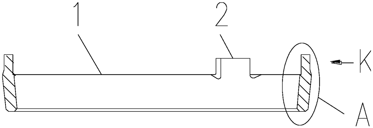
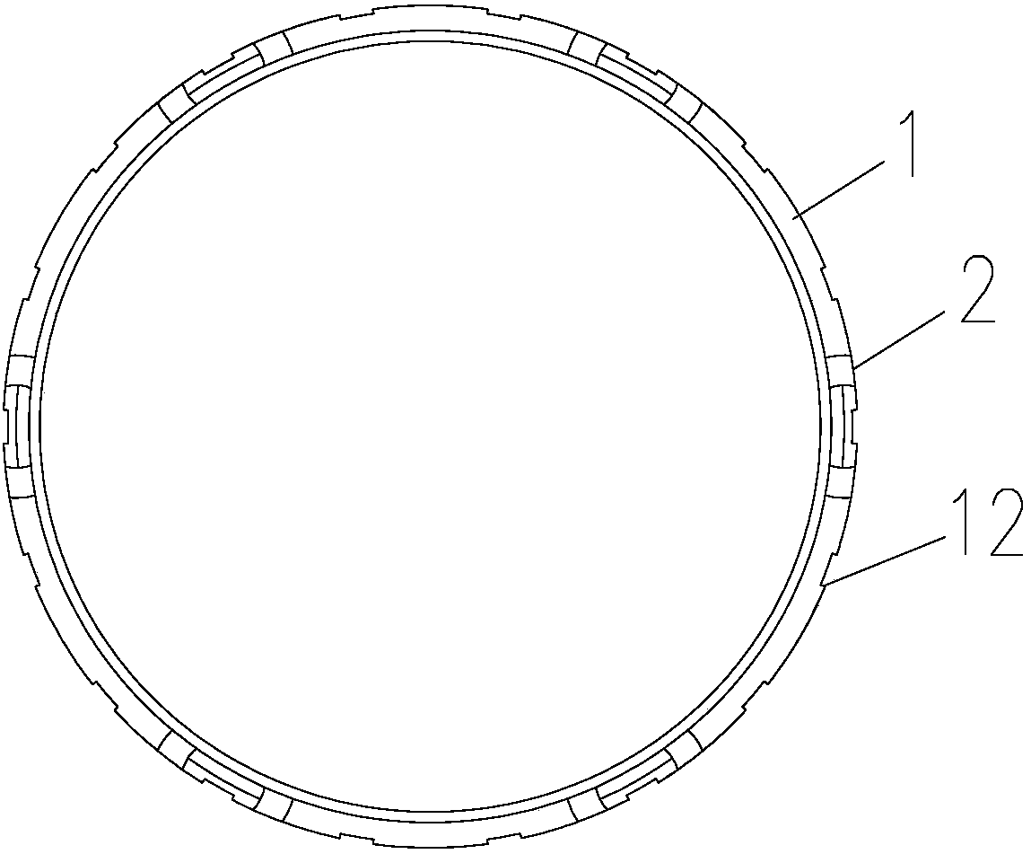
[0027] Such as Figure 1-Figure 4 Shown is a specific embodiment of a heat treatment method for a synchronizer intermediate ring of the present invention. The intermediate ring includes a cone ring body 1 and several prongs 2 arranged on the cone ring body 1. The heat treatment process of the intermediate ring includes the following steps:

[0028] S1, subjecting the intermediate ring to quenching and tempering treatment; preferably, the hardness of the intermediate ring after quenching and tempering satisfies 240-280 HV.

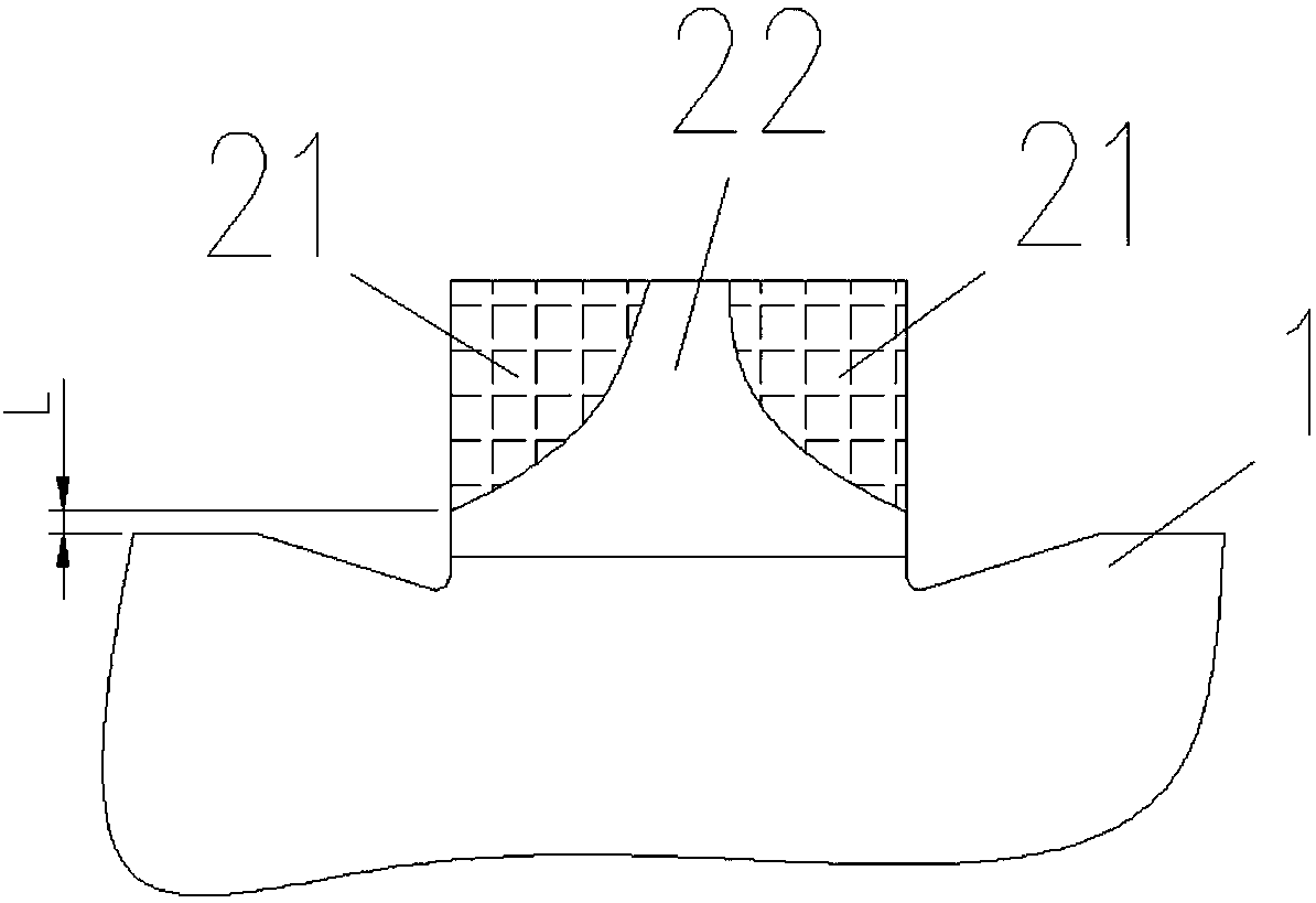
[0029] S2, according to the contact size of the claw 2 and other parts when the claw 2 is working, divide the claw 2 into an edge strengt...


PUM

PropertyMeasurementUnit
hardnessaaaaaaaaaa
hardnessaaaaaaaaaa
depthaaaaaaaaaa

Abstract

The invention belongs to the technical field of synchronizers and particularly relates to a heat treatment method for a middle ring of a synchronizer. The middle ring comprises a cone ring body and aplurality of raised claws disposed on the cone ring body. The heat treatment method comprises: S1, quenching and tempering the middle ring, S2, dividing the raised claw into an edge strengthening zoneand a connecting zone at two corners, S3, putting the edge strengthening zone of the raised claw into a high frequency inductor and carrying out high frequency induction quenching, and S4, temperingthe middle ring. The invention also relates to a middle ring structure prepared through a heat treatment method. The edge strengthening zone of the raised claw of the middle ring is subjected to quenching and tempering heat treatment so that the hardness, strength and wear resistance of the claw edge strengthening zone are improved. The connecting zone of the claw edge strengthening zone of the raised claw is not subjected to high-frequency induction quenching heat treatment and only is subjected to quenching and tempering treatment so that the raised claw has a certain toughness.

Description

technical field [0001] The invention belongs to the technical field of synchronizers, and in particular relates to a heat treatment method for an intermediate ring of a synchronizer and an intermediate ring structure. Background technique [0002] The synchronizer is a very important part in the car transmission system, which makes the car's speed change process very smooth and reliable, and the intermediate ring is a very important part of the synchronizer. The intermediate ring includes a conical cone ring and a ring connected to the ring Several claws on the gear, the claws can cooperate with the claw holes on the gear to be combined, and the intermediate ring is connected to the gear to be combined to rotate synchronously, and the outer cone surface is in contact with the inner cone surface of the synchronous ring, and with the contact tightness The friction between the two is constantly increasing, which drives the synchronous ring and the intermediate ring to rotate sy...

Claims


Application Information

Patent Timeline
Patent Type & Authority Applications(China)
IPC IPC(8): C21D1/25C21D1/10C21D9/40F16D23/02
CPCF16D23/02C21D1/10C21D1/25C21D9/40F16D2300/06Y02P10/25
Inventor 谢珊谢释斋
Owner 江苏持华科技有限公司
Why Eureka
Try Eureka