Method and system for increasing compact oil storage layer recovery ratio

A technology for tight oil and recovery factor, applied in the fields of fluid production, earthwork drilling, sustainable manufacturing/processing, etc. Improve sweep volume, improve oil washing efficiency, and prevent gas channeling

Inactive Publication Date: 2019-02-26
PETROCHINA CO LTD
View PDF5 Cites 1 Cited by
  • Summary
  • Abstract
  • Description
  • Claims
  • Application Information

AI Technical Summary

Problems solved by technology
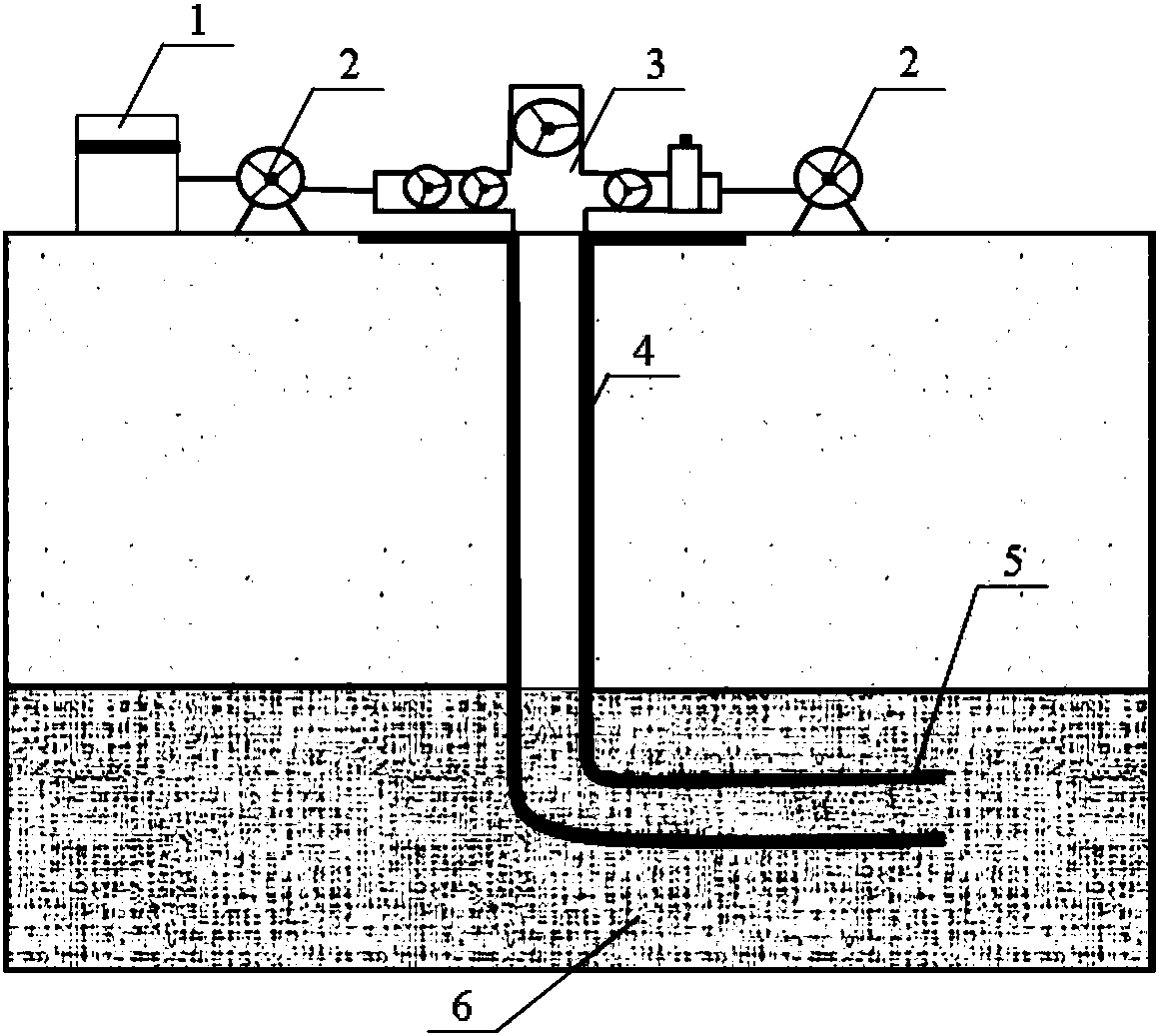
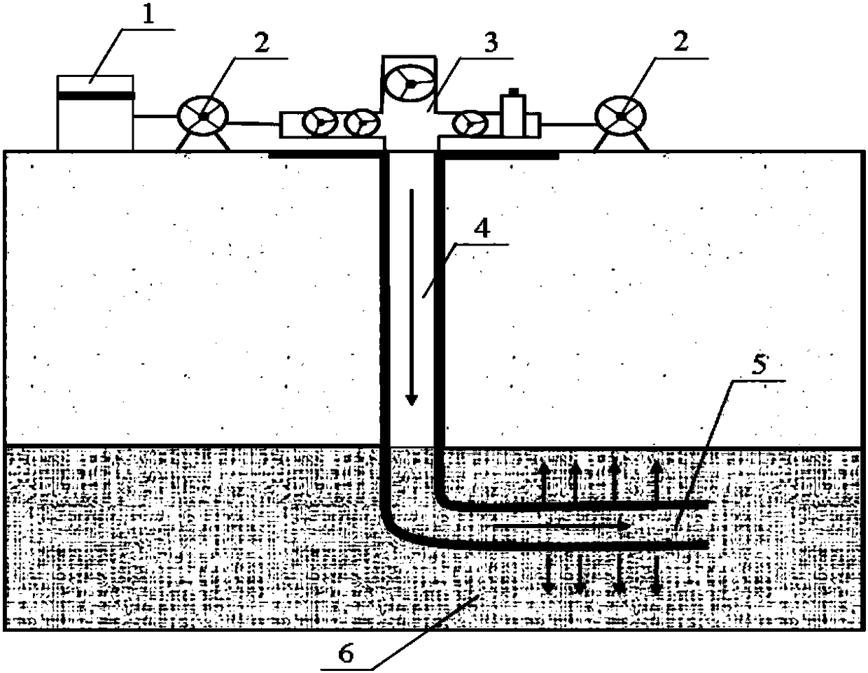
Although CO 2 Huff and puff recovery can increase the production of low-production wells, but it cannot play the role of plugging and regulating flooding, and CO2 is prone to occur during the oil displacement process. 2 Gas channeling, limited degree of recovery improvement

Method used


Image

  • Method and system for increasing compact oil storage layer recovery ratio
  • Method and system for increasing compact oil storage layer recovery ratio
  • Method and system for increasing compact oil storage layer recovery ratio

Examples


Embodiment 1

[0034] Put the tight oil core in the core holder, inject saturated water first, and then inject saturated oil to obtain a simulated tight oil reservoir; among them, the inner diameter of the tight oil core is 2.56cm, and the length is 10.5cm, which simulates the tight oil reservoir The permeability is 0.11mD.

[0035] Supercritical CO 2 , polyoxyethylene lauryl polyoxypropylene ether (C 12 E. 9 P 3 ) and co-solvent amyl alcohol are mixed uniformly in a mass ratio of 100:1:3 to obtain supercritical CO 2 Mix fluids.

[0036] First inject water into the above simulated tight oil reservoir for water flooding, the injection rate of water is 0.5PV; then inject the above supercritical CO2 into the simulated tight oil reservoir 2 Mixed fluid, supercritical CO 2 The injection volume of the mixed fluid is 0.2PV, the well is shut down, and the well is soaked for 24h under the conditions of a temperature of 60°C and an absolute pressure of 16MPa, and then the well is opened for prod...

Embodiment 2

[0039]Put the tight oil core in the core holder, inject saturated water first, and then inject saturated oil to obtain a simulated tight oil reservoir; among them, the inner diameter of the tight oil core is 2.54cm, the length is 10.1cm, and the simulated tight oil reservoir The permeability is 0.14mD.

[0040] Supercritical CO 2 , polyoxyethylene lauryl polyoxypropylene ether (C 12 E. 9 P 3 ) and co-solvent amyl alcohol are mixed uniformly in a mass ratio of 100:0.8:2 to obtain supercritical CO 2 Mix fluids.

[0041] First inject water into the above simulated tight oil reservoir for water flooding, the injection rate of water is 0.5PV; then inject the above supercritical CO2 into the simulated tight oil reservoir 2 Mixed fluid, supercritical CO 2 The injection volume of the mixed fluid is 0.2PV, the well is shut down, and the well is soaked for 24h under the conditions of a temperature of 60°C and an absolute pressure of 16MPa, and then the well is opened for productio...

Embodiment 3

[0044] Put the tight oil core in the core holder, inject saturated water first, and then inject saturated oil to obtain a simulated tight oil reservoir. The permeability is 0.09mD.

[0045] Supercritical CO 2 , polyoxyethylene lauryl polyoxypropylene ether (C 12 E. 9 P 3 ) and co-solvent amyl alcohol are mixed uniformly in a mass ratio of 100:1:3 to obtain supercritical CO 2 Mix fluids.

[0046] First inject water into the above simulated tight oil reservoir for water flooding, the water injection rate is 0.3PV; then inject the above supercritical CO2 into the simulated tight oil reservoir 2 Mixed fluid, supercritical CO 2 The injection volume of the mixed fluid is 0.2PV, the well is shut down, and the well is soaked for 24h under the conditions of a temperature of 60°C and an absolute pressure of 16MPa, and then the well is opened for production.

[0047] After testing, the recovery rate of the above-mentioned simulated tight oil reservoir is 26.5%.


PUM


Abstract

The invention provides a method and system for increasing the compact oil storage layer recovery ratio. The method for increasing the compact oil storage layer recovery ratio comprises the following steps that 1, water is injected into a compact oil storage layer for performing water drive; 2, a gas soluble surface active agent and super-critical CO2 are mixed to be uniform, super-critical CO2 mixed fluid is obtained, and the super-critical CO2 mixed fluid is injected into the compact oil storage layer obtained after water drive; 3, a well is shut in for soaking, then, the wheel is opened forexploiting. The method can effectively avoid CO2 gas channeling, and the compact oil storage layer recovery ratio is greatly increased.

Description

technical field [0001] The invention belongs to the technical field of oil and gas field development engineering, and in particular relates to a method and a system for improving the recovery rate of tight oil reservoirs. Background technique [0002] Tight oil is a kind of unconventional oil resource, which is the accumulation of oil formed without large-scale long-distance migration, which is sandwiched in or close to the tight reservoir of high-quality oil-generating formations. Because tight oil has the characteristics of complex accumulation mechanism, fine pore throat, low porosity and low permeability, and high content of interstitial materials, it is relatively difficult to exploit. [0003] Injecting carbon dioxide gas into the reservoir can effectively reduce the viscosity of crude oil, dissolve the reservoir glue layer, and increase the permeability, and has good application prospects in low-permeability reservoirs, high water-cut reservoirs and deep reservoirs; ...

Claims


Application Information

Patent Timeline
Patent Type & Authority Applications(China)
IPC IPC(8): E21B43/16
CPCE21B43/164Y02P90/70
Inventor 刘己全王鹏陈庆国
Owner PETROCHINA CO LTD
Why Eureka
Try Eureka