
Energy system control device for continuously sailing unmanned boat

An energy system and control device technology, which is applied in the direction of circuit devices, battery circuit devices, propulsion device engines, etc., can solve problems such as low utilization rate of solar energy, insufficient power supply of electric unmanned boats, and inability to realize weak power storage. The effect of improving sea area operation time, improving anti-interference performance and improving utilization rate

Pending Publication Date: 2019-02-26
SHANGHAI JIAO TONG UNIV
View PDF8 Cites 2 Cited by
  • Summary
  • Abstract
  • Description
  • Claims
  • Application Information

AI Technical Summary

Problems solved by technology

[0003] In the prior art, since the sunlight on the sea area is uncontrollable, when the sunlight is sufficient for a long time, when the solar lithium battery is fully charged, that is, when the electric energy converted by the solar panel is excessive, due to the For the purpose of solar lithium battery protection, the energy system control device on the electric unmanned boat usually cuts off the solar panel from the power supply circuit, and discharges the solar energy, resulting in a low utilization rate of solar energy
In the case of low sunlight, that is, when the solar panels can only generate weak power, the energy system control device of the electric unmanned boat cannot realize energy storage for the weak power, resulting in the possibility of insufficient power supply for the electric unmanned boat

Method used


Image

  • Energy system control device for continuously sailing unmanned boat

Examples


Embodiment Construction

[0015] In order to more clearly understand the above purpose, features and advantages of the present application, the present application will be further described in detail below in conjunction with the accompanying drawings and specific embodiments. It should be noted that, in the case of no conflict, the embodiments of the present application and the features in the embodiments can be combined with each other.

[0016] In the following description, a lot of specific details are set forth in order to fully understand the application, however, the application can also be implemented in other ways different from those described here, therefore, the protection scope of the application is not limited by the following disclosure Limitations of specific embodiments.

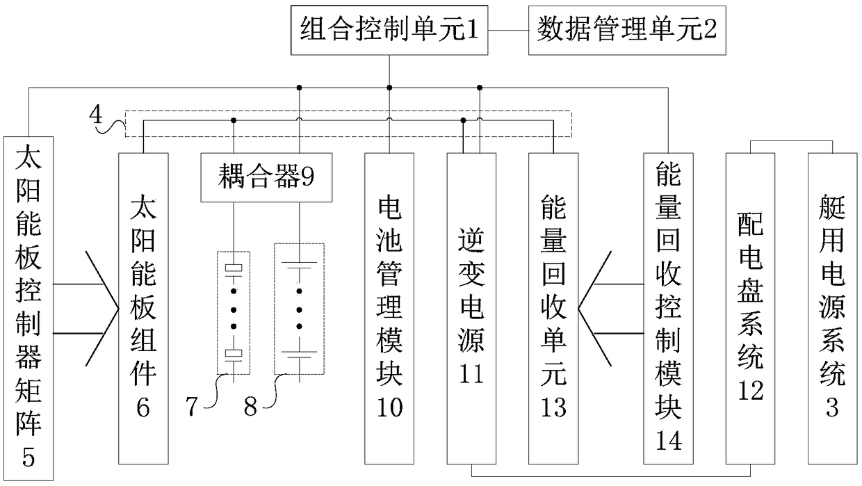
[0017] Such as figure 1 As shown, this embodiment provides an energy system control device for a continuous sailing unmanned boat, including: a solar panel assembly 6, a solar panel controller matrix 5, a DC bus 4, ...


PUM


Abstract

The application discloses an energy system control device for a continuously sailing unmanned boat. The energy system control device comprises a solar panel component, a solar panel controller matrix,an inverter power supply, a switchboard system, a boat power supply system, a combined control unit, a coupler, a super capacitor component and a lithium battery component; wherein the control end ofthe coupler is connected to the output end of the combined control unit; the power input end of the coupler is connected to the solar panel component through a DC bus; the first energy storage end ofthe coupler is connected to the super capacitor component; the second energy storage end of the coupler is connected to the lithium battery component; and the power output end of the coupler is connected to the inverter power supply. Through a technical solution implemented by the combined control unit in the present application, the solar energy utilization ratio of the unmanned boat is improved, and the offshore working time of the unmanned boat is prolonged, thereby realizing the continuous sailing of the unmanned boat throughout the year.

Description

technical field [0001] The present application relates to the technical field of unmanned boats, in particular, to an energy system control device for continuous sailing unmanned boats. Background technique [0002] The unmanned boat is a new type of offshore operation platform. By carrying different application modules on the unmanned boat, it can perform operations such as patrolling, sea area surveying and water quality testing around the clock. Combining solar lithium battery technology with unmanned boat technology, the electric unmanned boat is equipped with solar lithium batteries to provide power for the electric unmanned boat, so that the electric unmanned boat can sail on the sea for a long time and complete the long-term sea area Operation. [0003] In the prior art, since the sunlight on the sea area is uncontrollable, when the sunlight is sufficient for a long time, when the solar lithium battery is fully charged, that is, when the electric energy converted by ...

Claims


Application Information

Patent Timeline
Patent Type & Authority Applications(China)
IPC IPC(8): H02J7/34H02J7/35B63H21/17
CPCB63H21/17B63H2021/171H02J7/345H02J7/35
Inventor 金克帆易宏梁晓锋王鸿东
Owner SHANGHAI JIAO TONG UNIV
Learn More