Rotorcraft double-mechanical-arm target positioning and grabbing system and method

A dual robotic arm, target positioning technology, applied in the field of unmanned aerial vehicles, can solve the problems of difficult to stabilize the center of gravity, cumbersome line connection operation, single identification object, etc., to achieve the effect of improving overall reliability, wide application prospects, flexible and accurate positioning

Active Publication Date: 2019-03-01
HUNAN UNIV
View PDF7 Cites 23 Cited by
  • Summary
  • Abstract
  • Description
  • Claims
  • Application Information

AI Technical Summary

Problems solved by technology

[0006] (1) In the prior art, the rotor flying manipulators are all single-arm systems, which are difficult to stabilize the center of gravity, have fewer degrees of freedom, and the grasping objects are easily restricted;
[0007] (2) In the existing technology, most rotor flight manipulator systems are not equipped with multi-vision sensors and cannot interact with the environment in real time. Most of them are grasped by manual control, and no recognition and grasping system based on vision and manipulator planning has been formed;
[0008] (3) In the existing technology, the rotor flying manipulator system does not use a deep convolutional network to detect and recognize targets in the environment, so most of them have a single recognition object, do not have recognition diversity, and the recognition accuracy is low and the robustness is poor
[0009] (4) In the existing technology, the rotor flight manipulator system does not have a power supply and communication centralized module on the hardware. In the process of hardware and software connection and debugging, there are a lot of cumbersome line connection operations, and it is difficult to install, and it is easy to cause wiring Mistakes lead to damage to important modules and may lead to an unstable center of gravity

Method used


Image

  • Rotorcraft double-mechanical-arm target positioning and grabbing system and method
  • Rotorcraft double-mechanical-arm target positioning and grabbing system and method
  • Rotorcraft double-mechanical-arm target positioning and grabbing system and method

Examples


Embodiment Construction

[0066] In order to make the objectives, technical solutions and advantages of the present invention clearer, the present invention will be further described in detail below with reference to the embodiments. It should be understood that the specific embodiments described herein are only used to explain the present invention, but not to limit the present invention.

[0067] In the prior art, the rotor-flying manipulators are all single-arm systems, which are difficult to stabilize the center of gravity, and the grasped objects are easily limited; most rotor-flying manipulator systems are not equipped with multi-vision sensors, cannot communicate with the environment in real time, and are mostly controlled manually. Grasping, the recognition and grasping system based on vision and robotic arm planning has not been formed.

[0068] The application of the present invention will be further described below in conjunction with specific analysis.

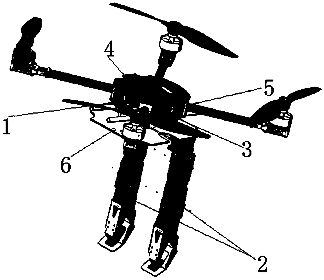
[0069] like figure 1 As shown in t...


PUM


Abstract

The invention belongs to the technical field of unmanned aerial vehicles and discloses a rotorcraft double-mechanical-arm target positioning and grabbing system and method. The rotorcraft double-mechanical-arm target positioning and grabbing system comprises a rotorcraft, an airborne computer, a double-mechanical-arm system, a flight controller, a power supply, a communication integrated circuit module and a visual sensor. The rotorcraft double-mechanical-arm target positioning and grabbing method comprises the steps that environmental video stream information is obtained in real time throughthe visual sensor, and a MobileNet-SSD model is adopted to train target recognizing and grabbing; a depth camera and AprilTag visual positioning are used in a switched mode so as to precisely obtain three-dimensional coordinate information of a recognized target; and FCL collision is introduced, and inverse kinematics operation of the mechanical arms are conducted through an RRT_Connect path planning algorithm, and thus spatial collision-free double-arm planning and grabbing are completed. According to the rotorcraft double-mechanical-arm target positioning and grabbing system and method, theability of an unmanned aerial vehicle to interact with the external environment can be effectively improved, and the autonomy property and accuracy of the rotor unmanned aerial vehicle from target recognizing, motion planning to stable grabbing is improved.

Description

technical field [0001] The invention belongs to the technical field of unmanned aerial vehicles, and in particular relates to a target positioning and grabbing system and method of a rotor-flying dual-manipulator arm. Background technique [0002] At present, the existing technologies commonly used in the industry are as follows: [0003] With the rapid development of UAV technology, multi-rotor UAVs have also begun to enter people's field of vision. Multi-rotor UAVs have the ability to take off, land and hover vertically. They are simple to operate, small in size and flexible in flight. Aerial photography detection, agriculture and forestry, security law enforcement, power grid inspection, border patrol and other fields have been more and more widely used. However, these are only at the level of observation, and do not effectively interact with the environment. For some dangerous or special tasks such as the investigation and transportation of dangerous goods, disaster res...

Claims


Application Information

Patent Timeline
Patent Type & Authority Applications(China)
IPC IPC(8): B64C27/08B64D1/22B25J9/16G06K9/00
CPCB64C27/08B64D1/22B25J9/1602B25J9/163B25J9/1664B25J9/1682B25J9/1697G06V20/13G06V20/10B64U10/10B64U50/19B64U2101/60
Inventor 谭建豪殷旺王耀南钟杭刘力铭余淼曹章尚畇凯
Owner HUNAN UNIV
Why Eureka
Try Eureka