Building method for abrasive bricks at end part of unloading chute of rotary hearth furnace

A technology of wear-resistant bricks and rotary hearth furnaces, which is applied in the direction of furnaces, furnace components, lighting and heating equipment, etc., and can solve the problem of reducing the service life of the feeding chute of the rotary hearth furnace, easily producing cracks at the end of the feeding chute, and affecting the rotation of the bottom. Furnace production and operation and other issues to achieve the effect of improving overall stability, ensuring production and operation, and extending service life

Active Publication Date: 2019-03-01
SHANGHAI BAOSTEEL IND TECHNOLOGICAL SERVICE
View PDF6 Cites 1 Cited by
  • Summary
  • Abstract
  • Description
  • Claims
  • Application Information

AI Technical Summary

Problems solved by technology

However, in the actual production process, it is difficult to truly exert the excellent performance of wear-resistant materials. The end of the discharge chute is prone to cracks and collapses. The material spiral is matched, which reduces the service life of the rotary hearth furnace feeding chute and seriously affects the production and operation of the rotary hearth furnace

Method used


Image

  • Building method for abrasive bricks at end part of unloading chute of rotary hearth furnace

Examples


Embodiment Construction

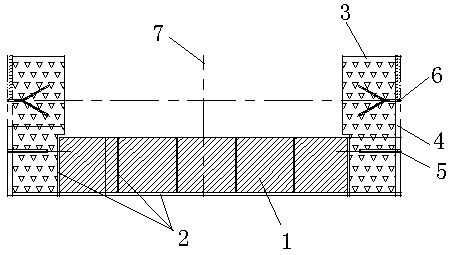
[0016] Example figure 1 As shown, the method for building wear-resistant bricks at the end of the discharge chute of the rotary hearth furnace of the present invention comprises the following steps:

[0017] Step 1. Measure the size of the steel structure shell at the end of the discharge chute, calculate and plan the masonry position of the wear-resistant brick 1 and the placement position of the wear-resistant block 2, and reserve on both sides of the steel structure shell at the end of the discharge chute The pouring zone 3, the masonry position of the wear-resistant brick 1 is located between the reserved pouring zone 3;

[0018] Step 2. Make the wear-resistant steel plate 4 and fully weld it on both sides of the steel structure shell at the end of the discharge chute. The inner side of the wear-resistant steel plate 4 is welded with the tie bars 5 to connect with the steel plate at the bottom of the shell. The V-shaped anchor nail 6, the tie bar 5 and the V-shaped anchor...


PUM


Abstract

The invention discloses a building method for abrasive bricks at the end part of an unloading chute of a rotary hearth furnace. According to the method, casting strips are reserved on the two sides ofa steel structured shell at the end part of the unloading chute; an abrasive brick building position is positioned between the reserved casting strips; wear resisting steel plates are welded on the two sides of the shell; tie pieces are welded on the inner sides of the wear resisting steel plates, and are connected with a steel plate at the bottom of the shell; anchoring nails are welded to gapsof the tie pieces in a crossed manner; in the abrasive brick building position, wear resisting stoppers are welded between adjacent abrasive bricks along the axis of the shell and welded at the positions, at the abrasive brick end faces, of the steel plate at the bottom of the shell, and the abrasive bricks are built; abrasive castable is cast in the reserved casting strips for compaction; and during casting, combined parts of the abrasive bricks and the reserved casting strips form slopes for supporting the abrasive bricks slightly projected. According to the method, the end part of the unloading chute is built as an organic whole, so that both wear and scouring are resisted, excellent heat stability is achieved, meanwhile, the overall stability of the structure is improved, the service life is prolonged, and the production operation of the rotary hearth furnace is guaranteed.

Description

technical field [0001] The invention relates to the technical field of repairing industrial furnaces and kilns, in particular to a method for building wear-resistant bricks at the end of a discharge chute of a rotary hearth furnace. Background technique [0002] Rotary hearth furnace is a new ironmaking process based on coal and hot air. It is a non-blast furnace ironmaking process developed in the past 40 years. The gradual development of rotary hearth furnace technology and its successful application have provided a channel for the treatment of solid waste in iron and steel plants, realized the recycling of resources in iron and steel enterprises, and reduced pollutant emissions. [0003] Rotary hearth furnace direct reduction technology is that iron ore powder (or laterite nickel ore, vanadium-titanium magnetite, sulfuric acid slag or metallurgical dust, dust ash, steelmaking and ironmaking sludge, etc.) The carbon-containing pellets are added into a rotary hearth furnac...

Claims


Application Information

Patent Timeline
Patent Type & Authority Applications(China)
IPC IPC(8): F27D1/16C04B35/66C04B35/10
CPCF27D1/1621F27D1/1626C04B35/10C04B35/66C04B2235/3826Y02P10/20
Inventor 童继恩沈伟国吴正怡胡德国陈胜鹏杨兵李生宇
Owner SHANGHAI BAOSTEEL IND TECHNOLOGICAL SERVICE
Why Eureka
Try Eureka