
Tapping and smoke exhausting system of rotary submerged arc furnace

A smoke exhaust system and submerged arc furnace technology, applied in furnaces, waste heat treatment, furnace components, etc., can solve the problems of disorderly discharge of smoke, increase of total smoke volume, increase of fan power loss, etc., and achieve precise and directional smoke exhaust , prevent splashing and overflowing, and solve dust environmental protection problems

Pending Publication Date: 2022-07-29
内蒙古鄂尔多斯电力冶金集团股份有限公司 +1
View PDF0 Cites 1 Cited by
  • Summary
  • Abstract
  • Description
  • Claims
  • Application Information

AI Technical Summary

Problems solved by technology

[0005] (1) The position of the tap hole of the traditional fixed submerged arc furnace is fixed, so the fixed tap exhaust system cannot solve the problem that the tap hole of the rotary electric furnace is not fixed; because the position of the tap hole of the rotary submerged arc furnace varies with the ore The hot furnace rotates and changes, so it is impossible to use the traditional fixed fume collecting hood and flue for centralized tapping and dust collection, which makes it difficult to collect the flue gas of the rotary rotary submerged arc furnace;
[0006] (2) Conventional tapping flue gas collection adopts a large fume hood, which is installed above the tap hole. The distance between the fume hood and the tap hole is too large, resulting in poor flue gas collection effect during the tapping process; and the traditional fixed submerged arc furnace The flue gas flow direction cannot be changed by the fume hood. Due to changes in the furnace conditions, the flue gas volume during the tapping fume exhaust process varies. When the power of the fume exhaust fan is constant, once the flue gas splashes at the tap hole, Because the flue gas flow rate is too fast, even if the fan is fully turned on, the purpose of completely collecting smoke and dust cannot be achieved, which will cause part of the flue gas to be discharged disorderly and pollute the environment;
[0007] (3) Since a large amount of cold air enters the process of collecting flue gas in the conventional large fume hood, the total amount of flue gas that needs to be discharged increases significantly, and the power requirements for the exhaust fan increase accordingly, and the electric power of the fan will increase during operation. In addition, due to the low temperature of the mixed air, the temperature of the flue gas will be greatly reduced, resulting in the condensation and precipitation of saturated moisture in the flue gas in the pipeline and purification links, which will increase the risk of pipeline blockage, filter bag sticking, etc., and affect the normal operation of production
[0008] The above-mentioned problems make it difficult to achieve a good tapping and smoke exhaust effect at the taphole of the rotary submerged arc furnace at present, and there is an urgent need for a tapping and smoke exhaust system with good smoke and dust removal effect and suitable for the rotary submerged arc furnace

Method used


Image

  • Tapping and smoke exhausting system of rotary submerged arc furnace
  • Tapping and smoke exhausting system of rotary submerged arc furnace
  • Tapping and smoke exhausting system of rotary submerged arc furnace

Examples


Embodiment 1

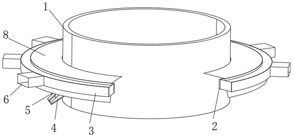
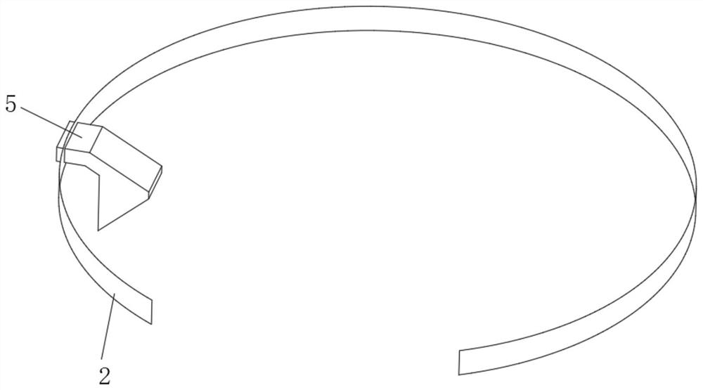
[0037] combine Figure 1-2 As shown, the embodiment of the present invention provides a rotary type submerged arc furnace tapping fume exhaust system, including a chute fume collecting hood 5, an annular baffle 2, an annular flue 3 and several fume exhaust hoods 6; the chute The fume collecting hood 5 includes a fume collecting port and a fume outlet, the fume collecting port of the chute fume collecting hood 5 is fixedly connected above the tap hole 4 of the submerged arc furnace, and the fume outlet of the chute fume collecting hood 5 is fixedly connected to the annular baffle plate 2; the annular baffle 2 surrounds the periphery of the submerged arc furnace 1, and rotates with the submerged arc furnace 1 together with the chute fume collecting hood 5;

[0038]The annular flue 3 is fixed on the periphery of the annular baffle 2, and a number of smoke exhaust hoods 6 are fixedly arranged on the outer side wall of the annular flue 3 at even intervals, and the smoke exhaust hoo...

Embodiment 2

[0040] The embodiments of the present invention make the following improvements on the basis of the above-mentioned embodiments:

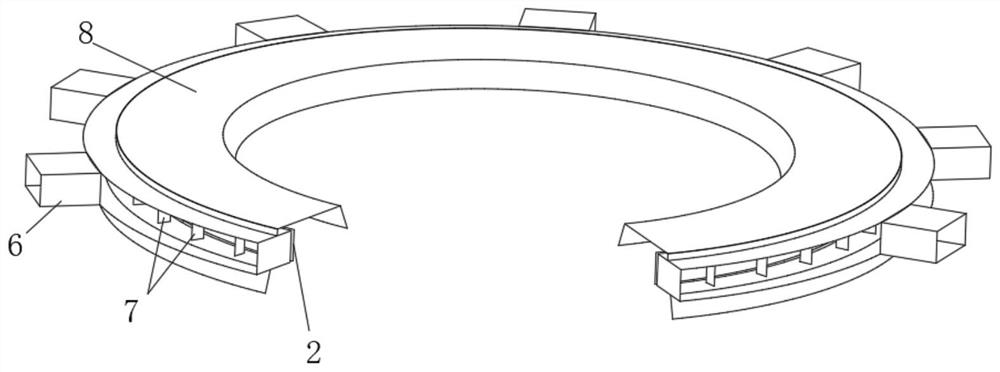
[0041] A gap of 100mm is left at the butt joint of the annular baffle 2 and the annular flue 3; an annular outer hood 8 is fixed above the annular duct 3, and the annular outer hood 8 can collect the overflowing molten iron ladle. The flue gas enters the annular flue through the gap between the annular flue 3 and the annular baffle 2 .

[0042] In the embodiment of the present invention, a gap of 80-150mm is left at the butt joint of the annular baffle 2 and the annular flue 3, so that the annular baffle 2 and the chute smoke collecting hood 5 rotate together with the submerged arc furnace 1, The annular baffle 2 can be prevented from rotating interference with the fixed annular flue 3 through the set gap; at the same time, an annular outer hood 8 with an n-shaped cross-section is fixed above the annular flue 3, so The annular outer fume hood 8 ca...

Embodiment 3

[0044] The embodiments of the present invention make the following improvements on the basis of the above-mentioned embodiments:

[0045] like image 3 As shown, several grilles 7 are arranged at intervals inside the annular flue, and two adjacent grilles 7 gather the flue gas collected by the chute fume collecting hood 5 in a small space, and discharge the smoke from the corresponding exhaust gas. The hood 6 is discharged; the fume exhaust hood 6 is a rectangular parallelepiped, and the width of the fume exhaust port of the fume exhaust hood 6 is smaller than the distance between the corresponding two adjacent grilles 7, which is convenient for the collection and discharge of the flue gas.

[0046] In the embodiment of the present invention, a valve for controlling the closing or opening of the smoke exhaust branch pipe is provided on the smoke exhaust branch pipe communicating with the smoke exhaust hood 6; , the valve on the smoke exhaust branch pipe of the corresponding s...


PUM


Abstract

The invention belongs to the technical field of submerged arc furnace smoke exhaust equipment, and particularly discloses a rotary type submerged arc furnace tapping smoke exhaust system. The system comprises a chute exhaust fume collecting hood, an annular flow baffle, an annular flue and a plurality of exhaust fume hoods, the chute exhaust fume collecting hood comprises an exhaust fume collecting port and an exhaust fume outlet, the exhaust fume collecting port is fixedly connected above an iron outlet of the submerged arc furnace, and the exhaust fume outlet is fixedly connected with an annular flow baffle; the annular flow baffle surrounds the periphery of the submerged arc furnace and rotates along with the submerged arc furnace together with the chute exhaust fume collecting hood; an annular flue is fixedly arranged on the periphery of the annular flow baffle, a plurality of smoke exhaust hoods are fixedly arranged on the outer side wall of the annular flue at intervals, and the smoke exhaust hoods communicate with smoke exhaust branch pipes of the dust removal system. Smoke collected by the chute smoke collecting hood penetrates through the annular flow baffle to enter the annular flue, and finally enters the smoke exhaust branch pipes through the smoke exhaust hood at the corresponding position to reach a dust removal system. The problems of tapping and smoke exhaust of the rotary submerged arc furnace can be solved, the smoke collection effect of the tap hole is improved, and the power loss of the smoke exhaust fan is reduced.

Description

technical field [0001] The invention belongs to the technical field of smoke exhaust equipment for submerged arc furnaces, and in particular relates to a rotary type submerged arc furnace iron tapping smoke exhaust system. Background technique [0002] Submerged arc furnace, also known as electric arc furnace or electric resistance furnace, is mainly used for reducing and smelting raw materials such as ore, carbonaceous reducing agent and solvent. The submerged arc furnace will generate a large amount of dust-containing flue gas during the iron smelting and tapping process, especially when the furnace hole is opened and blocked, the furnace gas is prone to splashing, and high-concentration dust-containing flue gas will be generated in a short time. If it is not collected in time Purification will cause great pollution to the environment. In addition, the flue gas from the tap hole has the characteristics of periodicity and large instantaneous flue gas volume. Tests show tha...

Claims


Application Information

Patent Timeline
Patent Type & Authority Applications(China)
IPC IPC(8): F27D17/00F27D3/15
CPCF27D17/001F27D3/1518F27M2001/02
Inventor 颜艺专邸俊明姚海英牛强
Owner 内蒙古鄂尔多斯电力冶金集团股份有限公司
Learn More