Efficient smoke condenser

A flue gas condenser and high-efficiency technology, applied in steam/steam condensers, lighting and heating equipment, etc., can solve the problems of high cooling efficiency requirements of flue gas cooling devices, reduced heat exchange efficiency, and low assembly quality, etc. Ensure long-term use without maintenance, improve production efficiency, and improve cooling efficiency

Pending Publication Date: 2019-03-01
浙江干氏制冷设备有限公司
View PDF0 Cites 0 Cited by
  • Summary
  • Abstract
  • Description
  • Claims
  • Application Information

AI Technical Summary

Problems solved by technology

However, the current flue gas condensing device mainly uses U-shaped copper tubes and fins. During assembly, the staff needs to assemble the U-shaped copper tubes to the designated positions one by one. Once a U-shaped copper tube is installed in the wrong position, it will be damaged. It needs to be taken out and then reassembled, which has the disadvantages of low assembly efficiency and low assembly quality, and because the U-shaped copper pipes are tightly installed, it is difficult to weld when welding the elbow; A large amount of dust is trapped, and when passing through the flue gas condensation device, it will encounter moisture retention and accumulation, which will reduce the heat exchange efficiency; in addition, such as in the power or metallurgical industry, there is a large amount of wet flue gas desulfurized by the desulfurization tower that needs to be cooled in time and discharged Therefore, the cooling efficiency of the flue gas cooling device is required to be higher

Method used


Image

  • Efficient smoke condenser
  • Efficient smoke condenser
  • Efficient smoke condenser

Examples


Embodiment Construction

[0019] In order to enable those skilled in the art to better understand the solutions of the present invention, the technical solutions in the embodiments of the present invention will be clearly and completely described below in conjunction with the drawings in the embodiments.

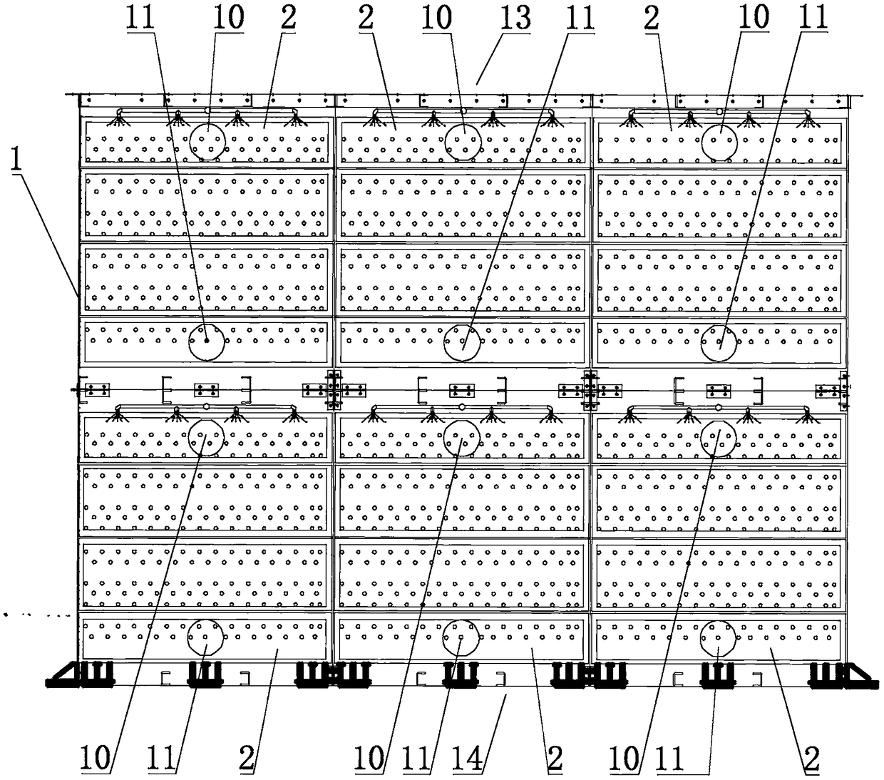
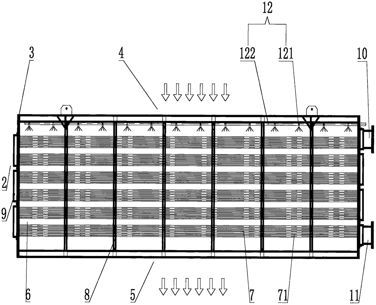
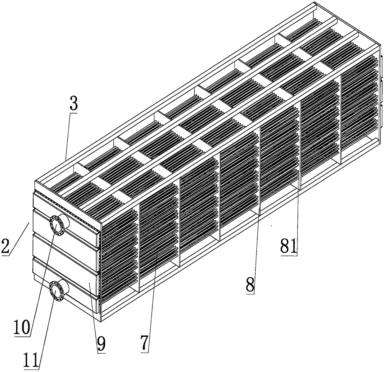
[0020] like figure 1 , figure 2 , image 3 , Figure 4 As shown, the present invention discloses a high-efficiency flue gas condenser, which includes a condensation chamber 1, and a plurality of condensation chambers 2 are arranged in the condensation chamber 1, and several condensation chambers 2 are sequentially connected and fixed in multiple rows and columns. Together, the condensation chamber 2 includes a frame 3, the top surface of the frame 3 is provided with a small smoke inlet 4, the bottom surface of the frame 3 is provided with a small smoke outlet 5, and the inside of the frame 3 is provided with a condensation device 6, the condensing device 6 is provided with a condensed water pipe ...


PUM


Abstract

The invention discloses an efficient smoke condenser. The efficient smoke condenser comprises a condensation chamber, multiple condensation cavities are formed in the condensation chamber, and are sequentially connected and fixed together in a multi-row multi-column manner, each condensation cavity comprises a rack, a condensation device is arranged in each rack and comprises a condensation waterpipe set, each condensation water pipe set comprises multiple equal-length flow dividing water pipes arranged in a horizontal direction manner, the connecting positions of the flow dividing water pipes, and the left end and the right end of the racks are welded and fixed, circulation holes are formed, the outer surfaces of the circulation holes are sleeved with multiple water tanks, spraying systems are arranged on smoke inlet small holes of the racks, and each spraying system comprises a spraying head and a spraying pipe connected with the spraying head. A large amount of high-temperature wetsmoke can be cooled at a time, meanwhile, water in smoke can be separated out, smoke heating is not needed, energy consumption is reduced, dust accumulation is avoided, heat exchange efficiency is improved, assembling and welding are convenient, and production efficiency and machining quality are improved.

Description

technical field [0001] The invention relates to a condenser, in particular to a high-efficiency flue gas condenser. Background technique [0002] With the rapid development of social economy, more and more flue gas is produced by industry, especially thermal power plants, which will produce a large amount of high-temperature gas. These high-temperature gases need to pass through a desulfurization device before being discharged into the air. Wet flue gas desulfurization is currently the most widely used desulfurization process in the market, and has the advantages of high desulfurization efficiency and simple structure. However, after passing through the desulfurization device, the flue gas has a high moisture content and is in a saturated state. When it contacts with the atmosphere, it will condense into countless small mist droplets and produce white water vapor, which will damage the city appearance and be misunderstood by residents as poisonous. Gas, causing panic and ot...

Claims


Application Information

Patent Timeline
Patent Type & Authority Applications(China)
IPC IPC(8): F28B1/02
CPCF28B1/02
Inventor 干苗根张雁雷张春明丁秋华金志刚周建成徐炜杰
Owner 浙江干氏制冷设备有限公司
Why Eureka
Try Eureka