Check patentability & draft patents in minutes with Patsnap Eureka AI!

Method for state monitoring and software upgrading of large-scale array system based on optical fiber communication

A software upgrade and system status technology, applied in optical multiplexing systems, transmission systems, optical fiber transmission, etc., can solve the problem of small number of subsystem monitoring and upgrading nodes, low communication efficiency, and mutual coupling of subsystems susceptible to interference, etc. problem, to shorten the time of software upgrade, avoid networking, and improve the anti-interference effect.

Active Publication Date: 2020-08-04
INST OF ELECTRICAL ENG CHINESE ACAD OF SCI
View PDF8 Cites 0 Cited by
  • Summary
  • Abstract
  • Description
  • Claims
  • Application Information

AI Technical Summary

Problems solved by technology

[0005] The purpose of the present invention is to overcome the shortcomings of the existing state monitoring and software upgrading methods, such as the small number of subsystem monitoring and upgrading nodes, low communication efficiency, and the mutual coupling between subsystems is susceptible to interference. It is not suitable for large-scale array multi-electric In the flat converter (MMC) flexible direct current transmission converter station and valve control system, a large-scale array system status monitoring and software upgrading method based on optical fiber communication is proposed

Method used


Image

  • Method for state monitoring and software upgrading of large-scale array system based on optical fiber communication
  • Method for state monitoring and software upgrading of large-scale array system based on optical fiber communication
  • Method for state monitoring and software upgrading of large-scale array system based on optical fiber communication

Examples


Embodiment Construction

[0032] The present invention will be further described below in conjunction with the drawings and specific embodiments.

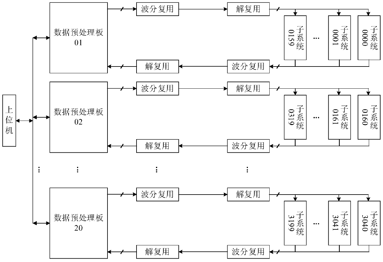
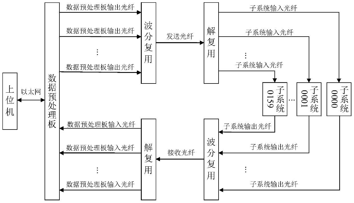
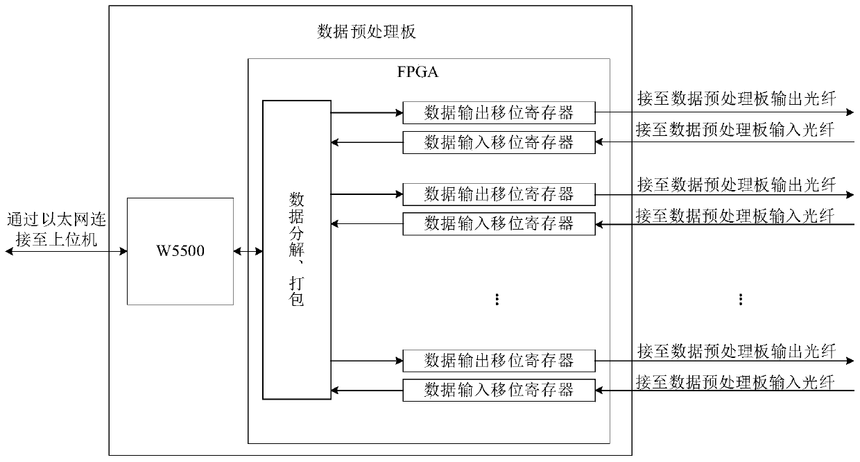
[0033] To figure 1 As an example, the typical system shown is composed of 3200 subsystems. Upgrade the software of the subsystem whose ID number is 0; the remaining subsystems will enter parameter monitoring after starting to run. During operation, the subsystem whose ID number is 5 under status monitoring will be modified once. Among them, steps 1 and 2 only need to be operated once when the system is assembled; during the normal use of the system, both are executed from step 3. figure 2 It is a schematic diagram of the data flow of the first group of subsystems in this typical system. The other groups of subsystems have the same structure and principle as the first group. image 3 For the principle block diagram of the data preprocessing board of the first group of subsystems, a data input shift register and a data output shift register are allocated to th...


PUM


Abstract

The invention discloses a large-scale array type system state monitoring and software upgrading method based on optical fiber communication. An upper computer is connected with multiple data pretreatment boards via the Ethernet. Each data pretreatment board is connected with a sub-system communicating with the same via an optical fiber, a wavelength division multiplexer and a demultiplexer; and asending path and a receiving path between each data pretreatment board and the sub-system occupy different optical fibers. Therefore, independent communication channels are constructed between the data pretreatment boards and the sub-systems. The upper computer distributes data packets to the data pretreatment boards via the Ethernet, and the data pretreatment boards analyze the data packets, andextract the data of each sub-system; the data of each sub-system is remotely transmitted to the corresponding sub-system via the optical fiber by using a wavelength-division multiplexing technology; the multiple sub-systems remotely transmit the data needing to be sent to a remote control terminal via the optical fibers by using the wavelength-division multiplexing technology; and the data pretreatment boards integrate the data of each sub-system, and sends the same to the upper computer via the Ethernet.

Description

Technical field [0001] The invention relates to a method for state monitoring and software upgrading of a large-scale array type multilevel converter (MMC) flexible direct current transmission converter station and a valve control system based on optical fiber communication. Background technique [0002] For large-scale array systems such as multilevel converter (MMC) flexible DC transmission converter stations and valve control systems, its status monitoring and software upgrades are a key issue after the system is put into use. The stand-alone system is relatively easy to achieve reliable and stable status monitoring and fast software upgrades. This type of large-scale array system uses a large number of electronic control units, and it is difficult to monitor and upgrade all subsystems at the same time. Industrial fieldbus multi-node networking has problems with the maximum number of nodes and communication stability, and the application environment of large-scale array syste...

Claims


Application Information

Patent Timeline
Patent Type & Authority Patents(China)
IPC IPC(8): H04J14/02H04B10/25G06F8/65
CPCG06F8/65H04B10/25891H04J14/0219H04J14/0272
Inventor 张剑颜朝鹏彭萌温旭辉
Owner INST OF ELECTRICAL ENG CHINESE ACAD OF SCI
Features
  • R&D
  • Intellectual Property
  • Life Sciences
  • Materials
  • Tech Scout
  • Unparalleled Data Quality
  • Higher Quality Content
  • 60% Fewer Hallucinations
Learn More