A radio frequency lap impedance measuring device and its manufacturing and measuring method
A technology of impedance measurement and radio frequency, which is applied in the direction of frequency measurement devices, measurement devices, and measurement of electrical variables, etc., can solve the problems of impracticable frequency sweep measurement of impedance, unsuitable measurement of radio frequency impedance, and high requirements for instruments, so as to achieve extended measurable Wide frequency range, wide impedance measurement range, and high measurement accuracy
- Summary
- Abstract
- Description
- Claims
- Application Information
AI Technical Summary
Problems solved by technology
Method used
Image
Examples
Embodiment 1
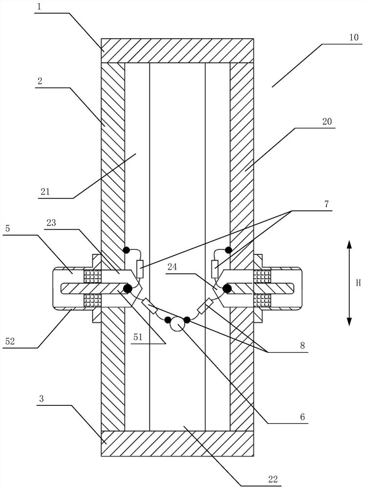
[0059] as attached figure 2 , 3 , Shown in 4 and 5, the specific embodiment of a kind of radio frequency lap impedance measurement device, comprises:
[0060] The cylinder body 20 , the top plate 1 located at the upper part of the cylinder body 20 , and the bottom plate 3 located at the lower part of the cylinder body 20 , an inner cavity is formed between the cylinder body 20 , the top plate 1 and the bottom plate 3 . The cylinder 20 further includes a shell 2 made of conductive material, and a cover plate 4 made of non-conductive material and matched with the shell 2;
[0061] One end is located in the inner cavity, and the other end is connected to the external test equipment 40 after passing through the housing 2, and is symmetrically arranged on the two test interfaces 5 on the opposite sides of the housing 2;
[0062] One end is located in the inner cavity, and the other end passes through the cover plate 4 and is connected to the external measured lap joint system 50...
Embodiment 2
[0070]A specific embodiment of a radio frequency bonding impedance measurement system based on the device described in Embodiment 1, the system includes: an impedance measuring device 10 and a measured bonding system 50 connected to the impedance measuring device 10, and the measured bonding system 50 includes Cabinet 9 and lap bar 12. The impedance measuring device 10 is connected to the cabinet 9 through the measuring clamp 6, and the bottom of the cabinet 9 is provided with an insulating pad 11, and the housing 2 of the impedance measuring device 10 is connected to the reference ground 13 through the bottom plate 3, and the cabinet 9 is connected to the ground through the lap bar 12 at the same time. Connect to reference ground 13.
[0071] as attached Figure 6 As shown, the tested bonding system 50 that is bonded with the impedance measuring device 10 simulates a size of 150 × 150 × 100mm 3 Cabinet 9 by 0.6 x 20 x 100mm 3 The grounding system of the flat bonding bar 12...
Embodiment 3
[0073] In order to design an impedance measuring device 10 that can measure the RF lap impedance in an actual system, this embodiment combines the device structure shown in Embodiment 1, and after comprehensively analyzing the performance of the existing measuring device, proposes an application RF bonding impedance measurement setup in real system. Wherein, the cylinder body 20 of the impedance measuring device 10 is mainly composed of two parts, one part is a metal shell 2 made of brass in the main body, and the other part is a cover plate 4 made of Bakelite material located on the opposite side of the metal shell 2 . A specific embodiment of the manufacturing method of the RF lap impedance measuring device as described in Embodiment 1, comprising the following steps:
[0074] S11) Select a square material made of conductive material, and set the mounting holes 23 for the test interface 5 on two opposite sides of the square material; the housing 2 made of brass adopts a 25×2...
PUM
 Abstract
Description
Claims
Application Information
 - R&D
- Intellectual Property
- Life Sciences
- Materials
- Tech Scout
- Unparalleled Data Quality
- Higher Quality Content
- 60% Fewer Hallucinations
Browse by: Latest US Patents, China's latest patents, Technical Efficacy Thesaurus, Application Domain, Technology Topic, Popular Technical Reports.
© 2025 PatSnap. All rights reserved.Legal|Privacy policy|Modern Slavery Act Transparency Statement|Sitemap|About US| Contact US: help@patsnap.com


