Space 3D printing system based on amorphous alloy superplastic welding

An amorphous alloy and 3D printing technology, applied in the direction of additive processing, etc., can solve the problems of the amorphous alloy 3D printing forming system with complex process, large device space, and unusability, so as to avoid the risk of high temperature crystallization and reduce the Effect of temperature gradient and prevention of cold welding

Pending Publication Date: 2019-03-08
CHINA ACADEMY OF SPACE TECHNOLOGY +1
View PDF8 Cites 7 Cited by
  • Summary
  • Abstract
  • Description
  • Claims
  • Application Information

AI Technical Summary

Problems solved by technology

However, the analysis found that the process of the amorphous alloy 3D printing forming system disclosed in this patent is relatively complicated, and it cannot be used in some special environments such as space microgravity conditions. The specific shortcomings are: (1) Since the laser device requires large energy , and the device occupies a relatively large volume, it is difficult to use high-energy lasers in the spacecraft to achieve 3D printing; (2) due to the use of preheated rollers for rolling, combined with ultrasonic vibration, the upper and lower layers of amorphous alloy The foil produces interatomic connections and rapidly cools down to form amorphous alloy parts with large-scale complex shapes and porous structures. Large temperature gradients often cause large thermal stress and residual stress. In complex space environments, It is easy to cause defects such as deformation and cracks in parts; (3) due to the load of the rocket launch and the limitation of the available space of the spacecraft, the space 3D printing system needs to be lightweight, convenient, miniaturized and automated

Method used


Image

  • Space 3D printing system based on amorphous alloy superplastic welding

Examples


Embodiment Construction

[0025] In order to make the object, technical solution and advantages of the present invention clearer, the present invention will be further described in detail below in conjunction with the accompanying drawings and embodiments. It should be understood that the specific embodiments described here are only used to explain the present invention, not to limit the present invention. In addition, the technical features involved in the various embodiments of the present invention described below can be combined with each other as long as they do not constitute a conflict with each other.

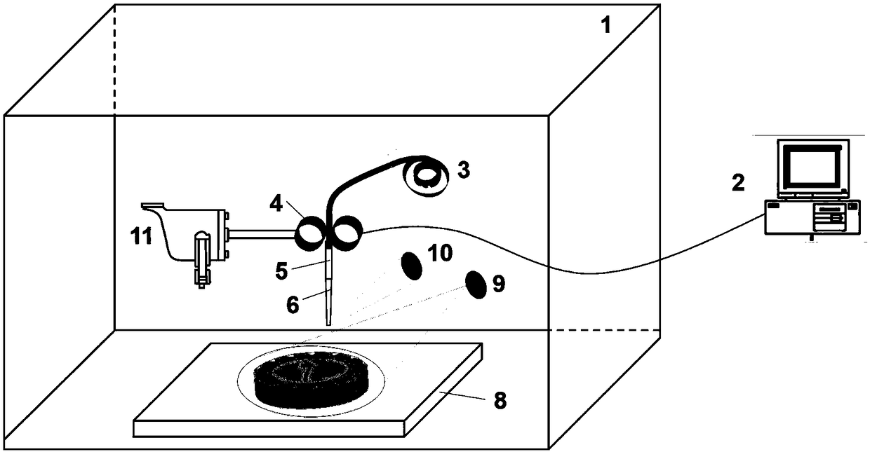
[0026] Aiming at the limitation of the payload launched by the rocket and the available space of the spacecraft, the present invention proposes a space 3D printing system suitable for the spacecraft. Such as figure 1 Shown is a schematic diagram of a spatial 3D printing system based on amorphous alloy superplastic welding according to an embodiment of the present invention. The 3D printing syst...


PUM

PropertyMeasurementUnit
glass transition temperatureaaaaaaaaaa
crystallization temperatureaaaaaaaaaa
yield stressaaaaaaaaaa

Abstract

The invention discloses a space 3D printing system based on amorphous alloy superplastic welding. The space 3D printing system comprises a shell (1), a control unit (2), a workbench (8) arranged inside the shell (1), an amorphous alloy material (3), a heating device, a mechanical loading device (11) and a conveying device, wherein the mechanical loading device (11) controls the speed of the conveying device and the pressure load of a spray head (6) according to the material use requirements of 3D printing molding parts, and the heating device performs local heating and welding on the amorphousalloy material (3) to realize part molding. According to the space 3D printing system based on the amorphous alloy superplastic welding, the heating device only heats an area near the spray head, thecrystallization risk of amorphous alloy under a long-time high-temperature condition is avoided, and the amorphous alloy is heated to a superplastic state of a supercooled liquid phase area to realize molding, a laser or electron beam heating device is cancelled, the equipment working stability is increased, and the space 3D printing system based on the amorphous alloy superplastic welding is especially suitable for in-orbit fabrication in the space environment.

Description

technical field [0001] The invention belongs to the technical field of metal 3D printer manufacturing, and more specifically relates to a spatial 3D printing system based on amorphous alloy superplastic welding. Background technique [0002] High-energy beam 3D printing (also known as additive manufacturing) is a kind of rapid prototyping technology. This technology transforms complex three-dimensional processing into simple two-dimensional processing through continuous physical layer superposition, which greatly reduces the difficulty of forming complex parts. Therefore, it is expected to solve the problem of forming and manufacturing complex structural parts that cannot be completed by traditional processing technology. In recent years, 3D printing technology has been gradually applied to the manufacture of actual products, among which the 3D printing technology of metal materials has developed particularly rapidly. According to statistics, the equipment and materials for...

Claims


Application Information

Patent Timeline
Patent Type & Authority Applications(China)
IPC IPC(8): B22F3/115B33Y10/00B33Y30/00
CPCB22F3/115B33Y10/00B33Y30/00
Inventor 赵少凡李宁张琪汪卫华
Owner CHINA ACADEMY OF SPACE TECHNOLOGY
Why Eureka
Try Eureka