Intelligent circumfluence pressure regulator

A pressure regulator and circulating flow technology, which is applied in the fields of metering devices, pressure regulating devices, cut-off devices, and current limiting devices, can solve the problems of large limitations in pressure regulation and stabilization, membrane safety accidents, and static characteristics of pressure and flow in regulators. Poor indicators and other issues, to achieve the effect of flexible and convenient layout, improved safety, and simple structure

Pending Publication Date: 2019-03-08
波普科技(唐山)有限公司
View PDF0 Cites 1 Cited by
  • Summary
  • Abstract
  • Description
  • Claims
  • Application Information

AI Technical Summary

Problems solved by technology

[0003] The above-mentioned pressure regulators are all purely mechanical semi-automatic adjustment devices, with single functions, large limitations in pressure regulation and stabilization, and a sharp drop in the outlet pressure of large flow rates—that is, the pressure and flow static characteristics of the pressure regulators are relatively poor! And it is impossible to realize remote automatic control; there are weak links in the film structure and maintenance is relatively frequent, and once the film is damaged, it is easy to cause various safety accidents
There is also the premise of the normal operation of the traditional pressure regulator is that a certain front pressure (inlet pressure) must be guaranteed, otherwise the pressure regulator will not work normally; and the traditional pressure regulator does not have remote controllability, and it is necessary to send someone to send a car On-site adjustment and disposal, etc.

Method used


Image

  • Intelligent circumfluence pressure regulator
  • Intelligent circumfluence pressure regulator
  • Intelligent circumfluence pressure regulator

Examples


Embodiment Construction

[0031] Below in conjunction with accompanying drawing and embodiment, further illustrate the present invention.

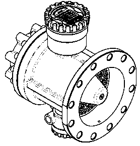
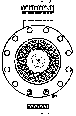
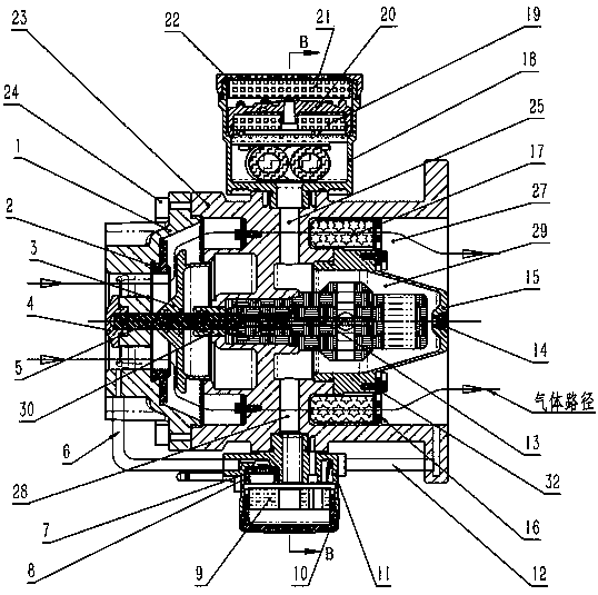
[0032] see Figure 1-Figure 4 , an intelligent circulating pressure regulator, consisting of a front valve body 1 and a rear valve body 23, the front valve body 1 and the rear valve body 23 are integrally formed by precision casting, the front valve body 1 is provided with a central shaft hole, and the center The shaft hole is provided with a main valve shaft 5, a diversion end cover 4, a wear-resistant sealing valve seat 2 and a diversion valve head 3. 2 The right side is provided with a diversion valve head 3, which is fixed on one end of the main valve shaft 5, the middle part of the main valve shaft is concentrically matched with the left end of the rear valve body 23 through the sealing guide sleeve 30, The other end is connected with the closed-loop linear actuator 13; the central shaft hole of the valve body 1 and the wear-resistant sealing valve seat 2 are...


PUM


Abstract

The invention discloses an intelligent circumfluence pressure regulator, which includes a front valve body and a rear valve body. The front valve body is provided with a center axle hole, the center axle hole is provided with a main valve shaft, a diversion end cover, a wear-resisting sealing valve seat and a diversion valve head, the diversion valve head is fixed to one end of the main valve shaft, the other end of the main valve shaft is connected with a closed-loop linear actuator, and the wear-resisting sealing valve seat is matched with the diversion valve head; the rear valve body is provided with an internal cavity and an external cavity which are mutually isolated, the closed-loop linear actuator is installed and fixed into the internal cavity, and the external cavity is a gas outflow channel; and the front valve body and the rear valve body are provided with pressure sensors correspondingly, the front valve body is provided with an inlet pressure sensor, and the rear valve body is provided with a pressure transmitter and a display shell. The intelligent circumfluence pressure regulator can easily realize six operation modes comprising an automatic pressure regulating mode,an automatic current limiting mode, an automatic low flow mode, a multi-period pressure reservation mode, a multi-period current limiting reservation mode and a gas total accumulation mode correspondingly, and meanwhile, the functions such as gas metering are achieved.

Description

technical field [0001] The invention relates to a pressure regulating device, a current limiting device, a metering device, and a cut-off device, in particular to an intelligent circulating voltage regulator which mainly focuses on pressure regulation and has multi-parameter control functions. Background technique [0002] The pressure regulator is a pressure-reducing device that automatically adjusts the gas outlet pressure to stabilize it within a certain range. According to the national standard "Urban Gas Pressure Regulator" GB-27790-2011, the gas pressure regulator is divided into two categories: direct acting pressure regulator and indirect acting pressure regulator. With the development of the gas industry, the pressure regulating equipment has also been continuously developed and improved for more than 100 years, and a wide variety of pressure regulators have appeared. For example: spring or gravity acting pressure regulator, Reynolds type pressure regulator, piston...

Claims


Application Information

Patent Timeline
Patent Type & Authority Applications(China)
IPC IPC(8): F16K17/26F16K31/06F16K37/00
CPCF16K17/26F16K31/0655F16K37/0091
Inventor 张立唐倪珊张立红曹雪梅安宁罗凤伟张立斌
Owner 波普科技(唐山)有限公司
Why Eureka
Try Eureka