Centrifugal micro-fluidic detector with flip type temperature control chamber

A detector and microfluidic technology, applied in the field of centrifugal microfluidic detectors, can solve problems such as accumulation, mechanical damage, and inability to integrate detection and analysis functions

Active Publication Date: 2019-03-08
BOAO BIOLOGICAL CO LTD
View PDF8 Cites 6 Cited by
  • Summary
  • Abstract
  • Description
  • Claims
  • Application Information

AI Technical Summary

Problems solved by technology

[0009] The purpose of the present invention is to provide a centrifugal microfluidic detector, which solves the problems existing in the conventional centrifugal microfluidic detector when it adopts the horizontal outlet method: the core components are driven by gears, racks or belts, and there is a problem for the user. The risk of mechanical damage requires more horizontal floor space, and the positioning accuracy between the axis of the centrifugal motor and the optical detection point is not high

Method used


Image

  • Centrifugal micro-fluidic detector with flip type temperature control chamber
  • Centrifugal micro-fluidic detector with flip type temperature control chamber
  • Centrifugal micro-fluidic detector with flip type temperature control chamber

Examples


Embodiment Construction

[0076] The present invention will be further described below in conjunction with the accompanying drawings, but the present invention is not limited to the following embodiments.

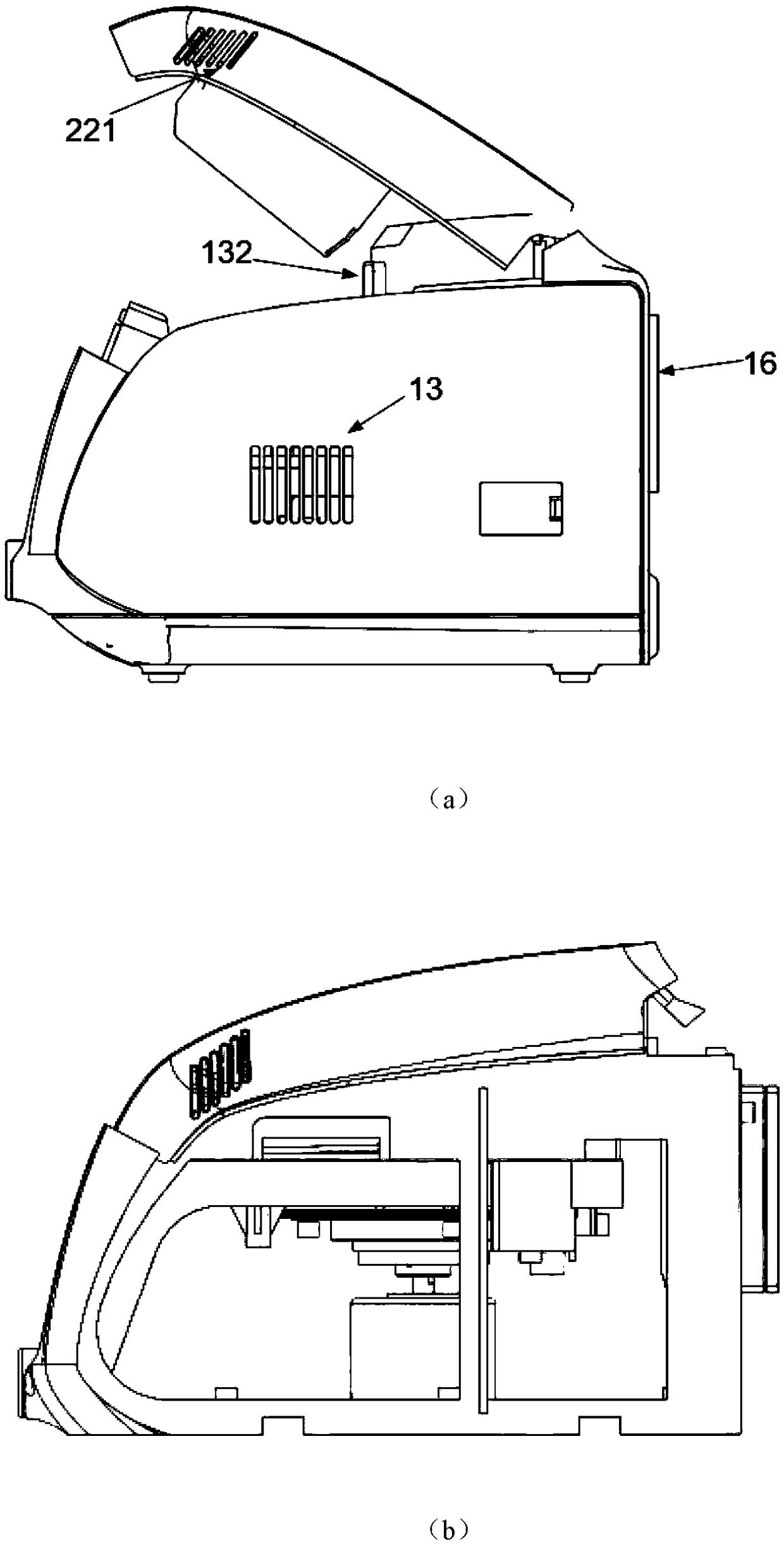
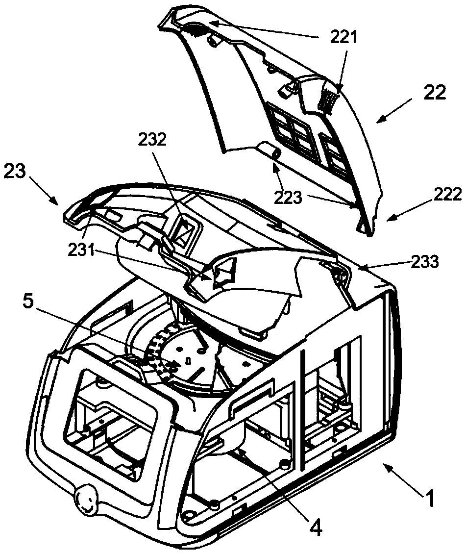
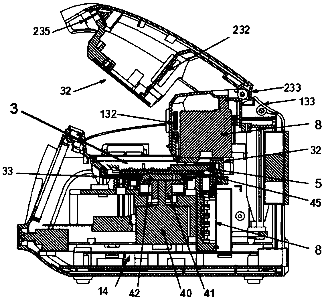
[0077] The centrifugal microfluidic detector provided by the present invention includes a detector cavity 1, an upper cover 2, a temperature control chamber 3 disposed in the detector cavity 1, a rotating motor assembly 4, an air outlet fan 6 and a detector assembly 8.

[0078]Wherein, the temperature control chamber 3 is an airtight chamber formed by the upper end cover 32, the cylinder body and the lower end cover 33 in order from top to bottom. The diameter-to-height ratio of the cylinder body is in the range of 6-16, and the height The range is 7-12 mm, and the diameter of the cylinder is 8-11 cm, which is a flat chamber. The outer surface of the upper end cover 32 is attached with a thin temperature controller (not marked in the figure) with the same shape and size, and the outer surface of th...


PUM


Abstract

The invention discloses a centrifugal micro-fluidic detector with a flip type temperature control chamber. The detector comprises a detector cavity, the temperature control chamber, a rotary motor assembly and a detector assembly, wherein the detector cavity is internally provided with the temperature control chamber; the temperature control chamber is a closed chamber formed by enabling an upperend cover, a cylinder body and a lower end cover to be matched with one another in sequence from top to bottom; the upper end cover is completely or partially connected into an upper cover, and the upper cover is arranged at an opening of the top of the detector cavity and is matched with the detector cavity in a flip mode; when the upper cover is closed, the upper end cover is matched with the cylinder body in a sealed mode; a temperature controller is attached to the outer surface of each of the upper end cover and the lower end cover; and a tray is arranged in the temperature control chamber. According to the centrifugal micro-fluidic detector, the volume of the temperature control space is decreased by adopting the flat chamber, in addition, an external air duct structure of the temperature control flat chamber is optimized, air inlets, air outlets, a guiding air duct and an air deflector at specific positions are designed, the sealing characteristics of all joints and flip movableparts are improved, and therefore the temperature of the internal chamber can be quickly and accurately controlled.

Description

technical field [0001] The invention relates to a centrifugal microfluidic detector, in particular to a centrifugal microfluidic detector with a flip-type temperature control chamber. Background technique [0002] Centrifugal microfluidic technology is a branch of microfluidic technology, which refers to the microfluidic technology that uses centrifugal force to drive liquid. Through chip design and centrifugal program control, unit operations such as sample processing, biochemical reactions, and result detection can be performed. integrated in one chip. The technology can be traced back to the late 1960s. Anderson et al. reported a centrifugal analyzer in 1969. Samples and reagents were added to the center of the disc, and the centrifugation allowed it to flow into the outer chamber through a motor. The rotation of the sensor allows the small chambers on the outside to pass through the light source in turn and detect the reaction results, thereby realizing the simultaneous...

Claims


Application Information

Patent Timeline
IPC IPC(8): G01N35/00B01L3/00
CPCG01N35/00G01N35/00584B01L3/50273B01L2400/0409G01N2035/00237G01N2035/00306G01N2035/00495G01N2035/00346
Inventor 潘良斌盛涛程振岳成亮潘汉灵
Owner BOAO BIOLOGICAL CO LTD
Why Eureka
Try Eureka