
Permanent magnet motor rotor processing technology and rotor assembly

A processing technology, permanent magnet motor technology, applied in the direction of electromechanical devices, manufacturing motor generators, magnetic circuit rotating parts, etc., can solve the problems of high cost, complicated process flow, and many steps

Inactive Publication Date: 2020-02-04
AIELEVATOR TIANJIN SCI CO LTD
View PDF15 Cites 3 Cited by
  • Summary
  • Abstract
  • Description
  • Claims
  • Application Information

AI Technical Summary

Problems solved by technology

[0003] The purpose of the present invention is to provide a permanent magnet motor rotor processing technology and rotor assembly, so as to alleviate the technical problems of many steps required, complex process flow and high cost in the prior art permanent magnet motor rotor processing technology

Method used


Image

  • Permanent magnet motor rotor processing technology and rotor assembly
  • Permanent magnet motor rotor processing technology and rotor assembly

Examples


Embodiment 1

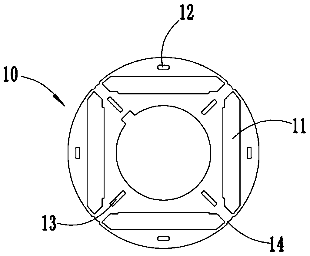
[0034] refer to figure 1 In the permanent magnet motor rotor processing technology provided in this embodiment, firstly, the parts to be stamped are stamped by a self-stacking riveting press to form a rotor piece 10 with a rotor groove 11, a riveting area and a welding joint 14, and then, the rotor piece 10 is dropped At the material station, the rotor slices 10 that are blanked each time are stacked on the previous punched rotor slice 10, and the two adjacent rotor slices 10 that are stacked together cooperate with each other through the riveting area, and there is no need to pass through the copper rod. To limit the position, the self-stacking riveting press presses down the upper mold of the blanking station, that is, the uppermost rotor piece 10 is stacked and riveted on the lower adjacent rotor piece 10, and the upper mold works continuously to form the adjacent rotor piece 10 are mutually riveted rotor cores. At this time, the axes of the rotor segments 10 of the rotor c...

Embodiment 2

[0068] This embodiment provides a rotor assembly, which is manufactured by the above-mentioned permanent magnet motor rotor processing technology.

[0069] The rotor assembly provided in this embodiment is manufactured by adopting the above-mentioned permanent magnet motor rotor processing technology, which ensures that the rotor cores are relatively fixed during the use of each adjacent rotor piece 10, and meets the use requirements of the permanent magnet motor. At the same time, the rotor The entire processing procedure is also less, reducing production costs.


PUM

PropertyMeasurementUnit
Heightaaaaaaaaaa

Abstract

The invention relates to a permanent magnet motor rotor processing technology and a rotor assembly, and relates to the technical field of permanent magnet synchronous submersible motors. The permanentmagnet motor rotor processing technology comprises the steps of stamping a to-be-stamped part into a rotor sheet with a rotor groove, a riveting area and a welding port through a self-laminating andriveting stamping machine; mutually laminating and riveting the plurality of rotor sheets to form a rotor core through the riveting area by the self-laminating and riveting stamping machine; completing the welding of adjacent rotor sheets in the rotor core at the welding port by using laser; assembling permanent magnets in the rotor grooves, and bonding magnetism isolating rings to two ends of therotor core; and drying and curing the rotor core. The rotor assembly is processing according to the permanent magnet motor rotor processing technology. The technical problems of multiple steps, complicated technological process and high cost of the permanent magnet motor rotor processing technology in the prior art are alleviated.

Description

technical field [0001] The invention relates to the technical field of permanent magnet synchronous submersible motors, in particular to a permanent magnet motor rotor processing technology and rotor assembly. Background technique [0002] With the application and popularization of permanent magnet synchronous submersible motors, the processing technology of permanent magnet submersible motor rotors on the market still draws on the processing technology of traditional induction asynchronous submersible motor rotors, but this kind of rotor processing technology is the Laminated rotor cores require copper rods or other tools to complete the positioning of multiple rotor pieces during lamination, ensuring that the axes of each rotor piece are collinear before completing the lamination forming process; due to copper rods limited error, and additional machining processes are required to control the size of the inner and outer diameters (for example, a broach is required to adjust...

Claims


Application Information

Patent Timeline
IPC IPC(8): H02K15/03H02K1/27
CPCH02K1/27H02K15/03
Inventor 叶纲王海滨爱德华·卡尔·曼蒂王斌
Owner AIELEVATOR TIANJIN SCI CO LTD
Learn More