A lens position adjustment mechanism for an optical system

A technology for adjusting mechanisms and optical systems, applied in optics, optical components, instruments, etc., can solve problems that are difficult to meet, difficult to clean, and easily damaged optical systems, and achieve the effects of accurate relative position, simple adjustment operation, and guaranteed stability

Active Publication Date: 2021-05-28
WUHAN LINGYUN PHOTOELECTRONICS SYST
View PDF0 Cites 0 Cited by
  • Summary
  • Abstract
  • Description
  • Claims
  • Application Information

AI Technical Summary

Problems solved by technology

In this optical path diagram, the adjustment of the distance between the objective lens and the flat lens is still sensitive to the effect of focusing, and the diameter of the spot is only Compared with the distance adjustment between the axicon lens and the flat lens, the sensitivity requirement is lower, as long as the center of the laser circle deviates slightly, it will cause a large loss of laser energy
[0003] At present, in order to achieve better focusing and precise machining and cutting, the distance between lenses is adjusted through a cage system structure (combined with guide rods, mirror frames, etc.), but this method has certain limitations. Disadvantages: First, the cage system is an open structure, and the external dust is easy to damage the optical system, which is difficult to clean and is not conducive to the maintenance of the optical system; second, there is no benchmark for the assembly of the cage system, and it is impossible to do it during debugging Precise and continuous adjustment of the relative position between the lens and the lens, between the lens and the objective lens
The existing cage system structure has been difficult to meet the requirements of [dust-free] and [precise and continuous adjustment]

Method used


Image

  • A lens position adjustment mechanism for an optical system
  • A lens position adjustment mechanism for an optical system
  • A lens position adjustment mechanism for an optical system

Examples


Embodiment Construction

[0029] The present invention will be further described in detail below in conjunction with the accompanying drawings and specific embodiments to facilitate a clear understanding of the present invention, but they do not limit the present invention.

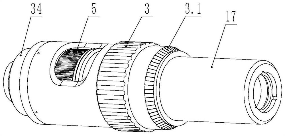
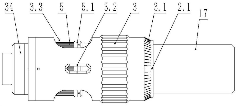
[0030] Such as Figure 2-5 Shown, the present invention comprises objective lens 1, the plano lens holder 4 of fixed plano-convex lens 7, the axicon lens holder 6 of fixed axicon lens 8, outer sleeve 3 and axicon lens adjustment sleeve 5, described objective lens 1, plano-convex lens 7 and the axicon lens 8 are coaxially arranged in turn; one end of the outer sleeve 3 is connected to the axial limit of the end of the objective lens 1, the inner wall of the outer sleeve 3 is threaded with the outer wall of the flat lens holder 4, and the flat lens holder 4 A first cavity 39 is provided between one end and the objective lens 1, the other end of the flat lens holder 4 is fixedly connected with one end of the axicon lens adjustment sl...


PUM


Abstract

The invention discloses a lens position adjustment mechanism for an optical system. It includes an objective lens, a flat lens holder, an axicon lens holder, an outer sleeve and an axicon lens adjustment sleeve, one end of the outer sleeve is connected to the end of the objective lens in an axial limit, and the inner wall of the outer sleeve is connected to the outer wall of the flat lens holder. Threaded connection, the other end of the flat lens holder is fixedly connected with one end of the axicon lens adjustment sleeve, the inner wall of the axicon lens adjustment sleeve is threaded with the outer wall of the axicon lens holder, the outer sleeve and the flat lens holder A first flat key structure is provided, a second flat key structure is provided between the axicon lens adjusting sleeve and the axicon lens holder, the end of the objective lens is fixedly connected with one end of the first flat key structure, and the axicon lens adjustment The other end of the sleeve is axially limitedly connected with the second flat key structure. The invention has a compact structure, the relative position of the inner optical lens can be realized only by adjusting the outer sleeve and rotating the adjustment knob, and the adjustment operation is simple and easy.

Description

technical field [0001] The invention belongs to the technical field of adjustment of precision optical systems in the laser processing industry, and in particular relates to a lens position adjustment mechanism for the optical system, which can realize arbitrary adjustment of the relative distance between the lenses and the lenses in a closed environment. Background technique [0002] Such as figure 1 The optical path diagram shown is a common optical path design in an optical system. The optical path diagram includes an axicon lens, two flat lenses and a set of objective lenses. In actual use, it is necessary to ensure the distance between the axicon lens and the flat lens as a whole relative to the objective lens. Adjustable, and secondly, the distance between the axicon lens and the plano lens also needs to be adjustable. In this optical path diagram, the adjustment of the distance between the objective lens and the flat lens is still sensitive to the effect of focusing,...

Claims


Application Information

Patent Timeline
Patent Type & Authority Patents(China)
IPC IPC(8): G02B7/02
CPCG02B7/021G02B7/023G02B7/026
Inventor 胡太富
Owner WUHAN LINGYUN PHOTOELECTRONICS SYST
Why Eureka
Try Eureka