
A Microstrip Array Antenna Structure That Can Improve the Isolation Between Antennas

A technology of microstrip array and antenna structure, which is applied in the direction of antenna array, separately powered antenna array, antenna grounding switch structure connection, etc., can solve problems such as electromagnetic interference, achieve flat isolation performance, enhance decoupling effect, and reduce design difficulty Effect

Active Publication Date: 2020-11-17
SHANGHAI SPACEFLIGHT ELECTRONICS & COMM EQUIP RES INST
View PDF8 Cites 0 Cited by
  • Summary
  • Abstract
  • Description
  • Claims
  • Application Information

AI Technical Summary

Problems solved by technology

Especially on ships, in order to meet the needs of communication and navigation, the number of antennas on the shipboard platform has doubled, and multiple antennas work simultaneously in a small area, which will cause serious electromagnetic interference

Method used


Image

  • A Microstrip Array Antenna Structure That Can Improve the Isolation Between Antennas
  • A Microstrip Array Antenna Structure That Can Improve the Isolation Between Antennas
  • A Microstrip Array Antenna Structure That Can Improve the Isolation Between Antennas

Examples


Embodiment Construction

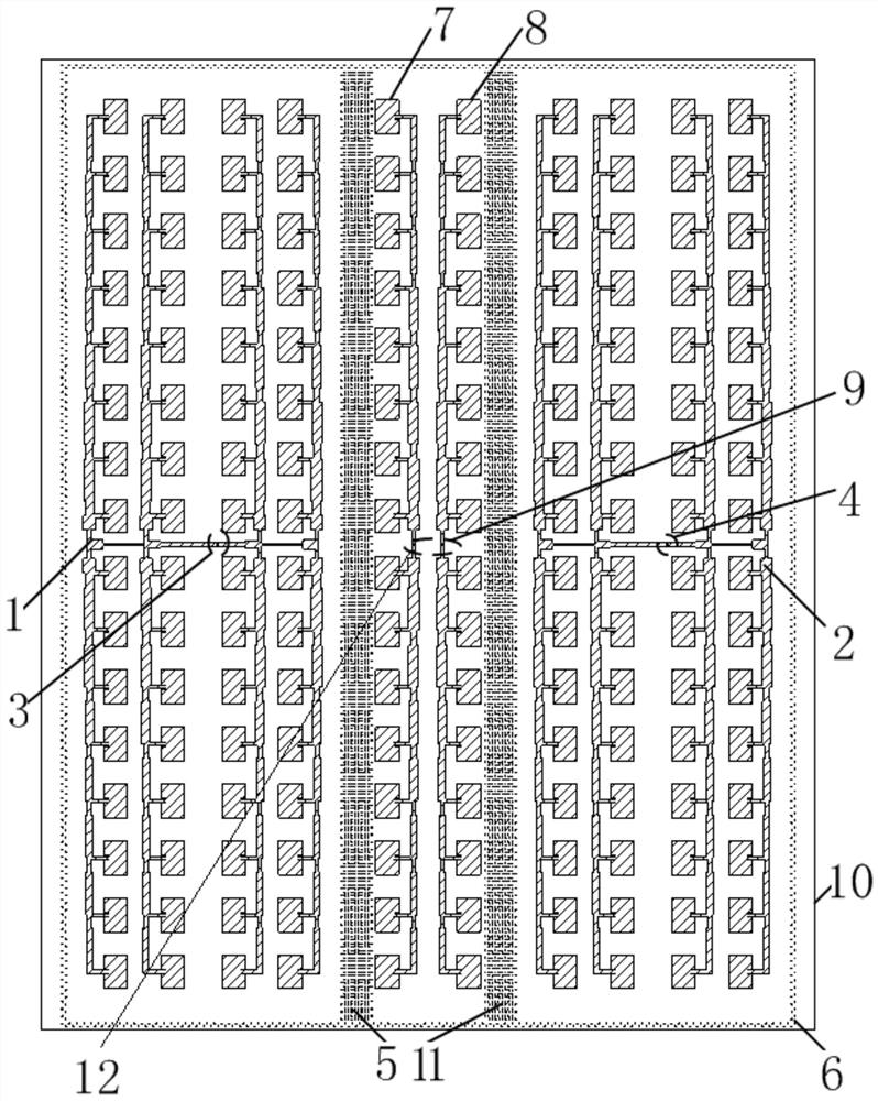
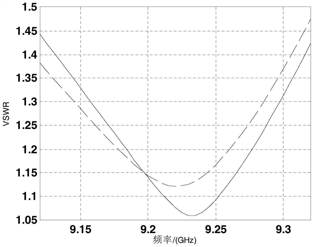
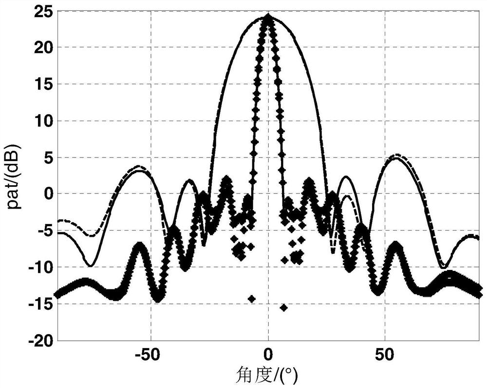
[0037] The following will combine Figure 1 to Figure 4 The structure of the microstrip array antenna that can improve the isolation between antennas provided by the present invention is described in detail. This embodiment is implemented on the premise of the technical solution of the present invention, and the detailed implementation mode and specific operation process are given. However, The protection scope of the present invention is not limited to the following embodiments, those skilled in the art can modify and embellish it within the scope of not changing the spirit and content of the present invention.

[0038] Please refer to figure 1 , the present invention provides a microstrip array antenna structure that can improve the isolation between antennas, which includes: a high-frequency dielectric board 10, the front of the dielectric board 10 is etched with transmitting microstrip array antennas 1, receiving The microstrip array antenna 2, the first isolation line ar...


PUM


Abstract

The invention relates to a microstrip array antenna structure capable of improving isolation between antennas. The structure comprises a dielectric board; the front side of the dielectric board is provided with transmitting microstrip array antennas and receiving microstrip array antennas at intervals; the back surface of the dielectric board is a metal floor; first isolated antenna arrays and second isolated antenna arrays are introduced between the transmitting microstrip array antennas and the receiving microstrip array antennas; first metallized through holes are introduced between the transmitting microstrip array antennas and the first isolated antenna arrays; second metallized through holes are introduced between the receiving microstrip array antennas and the second isolated antenna array; and at least one circle of peripheral metallized through holes are formed along the outer sides of the transmitting microstrip array antennas and the receiving microstrip array antennas. Thefirst isolated antenna arrays and the second isolated antenna arrays are introduced between the transmitting microstrip array antennas and the receiving microstrip array antennas, so that the isolation performance is improved by 7.5dB under the condition that the distance between the transmitting and receiving antennas is unchanged, and the isolation between the transmitting and receiving antennasin a working frequency band is smaller than 70dB; and the structure is suitable to transmit and receive electromagnetic waves in a continuous wave radar system.

Description

technical field [0001] The invention relates to the technical field of microstrip antennas, in particular to a microstrip array antenna structure capable of improving the isolation between antennas. Background technique [0002] Compared with commonly used microwave antennas, microstrip antennas have the following outstanding advantages: [0003] 1. Light weight, relatively small volume, low profile, and can conform to aircraft and other carriers; [0004] 2. Easy to make and modulate, low production cost, suitable for mass production; [0005] 3. The performance of easy integration has great advantages in the application of millimeter wave band; [0006] 4. The electrical performance is diversified. By changing the design of the microstrip element, various polarization modes can be easily obtained, and dual-frequency and multi-frequency can also be realized. [0007] The unique performance of the microstrip antenna determines its wide application background. At present, ...

Claims


Application Information

Patent Timeline
Patent Type & Authority Patents(China)
IPC IPC(8): H01Q21/00H01Q21/08H01Q1/52H01Q1/50H01Q1/38
CPCH01Q1/38H01Q1/50H01Q1/525H01Q21/00H01Q21/0075H01Q21/08
Inventor 薛玲珑于守江叶声林鑫郭一帆
Owner SHANGHAI SPACEFLIGHT ELECTRONICS & COMM EQUIP RES INST
Learn More