Flexible circuit board full-automatic wire stripping, terminal pressing and shell insertion method and device

A fully automatic, wire-stripping technology, applied in circuit/collector parts, assembly/disassembly of contacts, electrical components, etc. Problems such as the insufficiency of the terminal shell to achieve the effect of improving the quality of the shell, reducing the defective rate of the shell, and improving the quality of the assembly

Pending Publication Date: 2019-03-08
东莞市超日自动化设备科技有限公司
View PDF9 Cites 10 Cited by
  • Summary
  • Abstract
  • Description
  • Claims
  • Application Information

AI Technical Summary

Problems solved by technology

At present, most of the thread splitting methods are manual thread splitting, such as cutting with scissors. This method is inefficient and easily cuts the thread; However, the structure of these automatic branching devices is complex, the cost is high, and the operation and maintenance are difficult
[0004] And, in the prior art, when the cable terminal is plugged into the shell, the cable terminal and the plastic shell are usually inserted in the same plane, which has many shortcomings, for example: 1. The cable terminal is not inserted in place, and the socket appears. Position deviation, etc., affect the stability and reliabil

Method used


Image

  • Flexible circuit board full-automatic wire stripping, terminal pressing and shell insertion method and device
  • Flexible circuit board full-automatic wire stripping, terminal pressing and shell insertion method and device
  • Flexible circuit board full-automatic wire stripping, terminal pressing and shell insertion method and device

Examples


Embodiment Construction

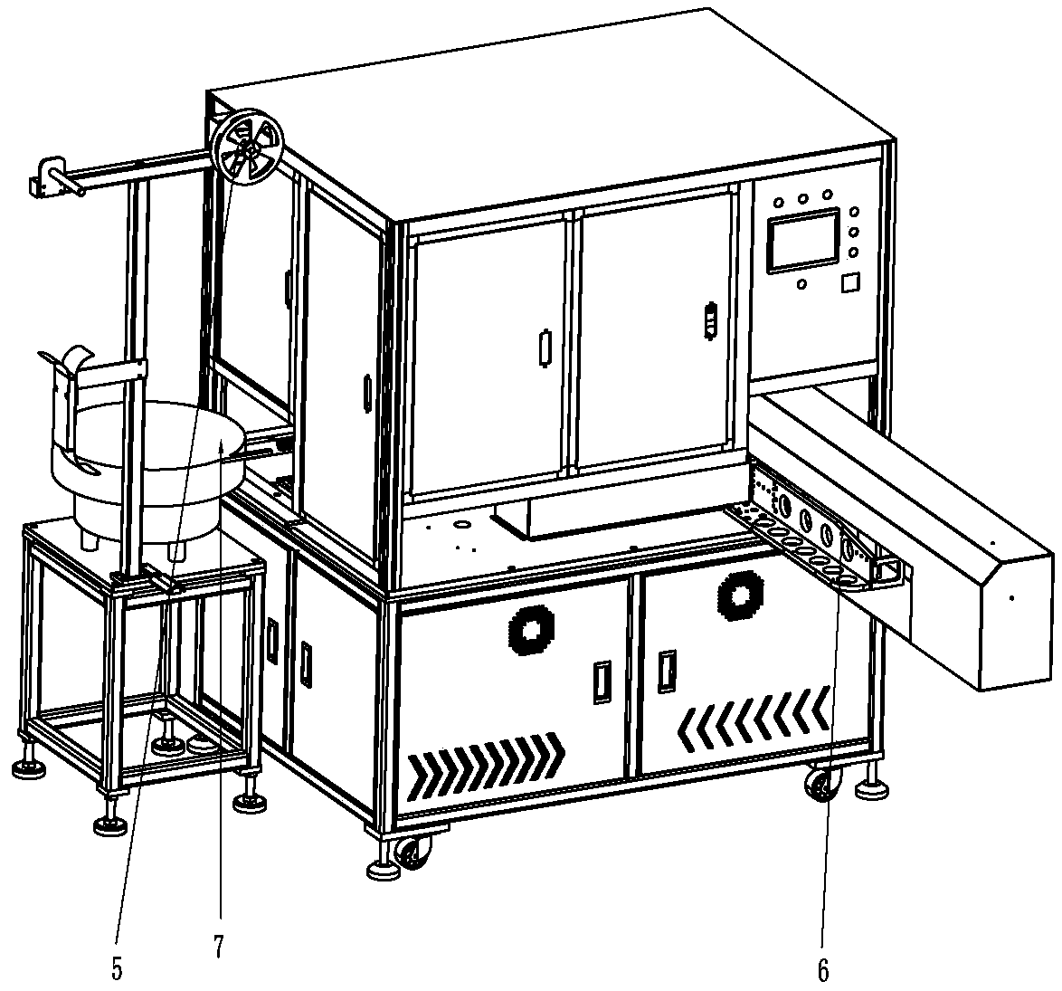
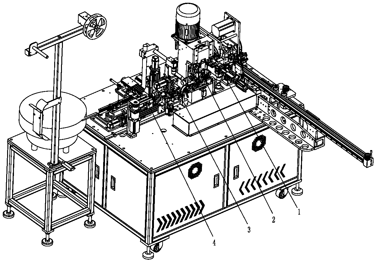
[0042] Please refer to Figure 1 to Figure 23 As shown, it shows the specific structure of the embodiment of the present invention.

[0043] A method for fully automatic wire stripping, crimping, and shell insertion of cables, which sequentially includes the steps of stripping, crimping, splitting, and inserting; And, the corresponding crimping device (integrated interlocking crimping module 2), branching device 3, housing device 4, other links (for example: stripping device 1, terminal strip supply end 5, cable supply end 6. The rubber shell supply end 7) can be realized by conventional technology, and there is no limitation here.

[0044] Next, according to the process, the three links of pressure end, branch line and socket are introduced one by one:

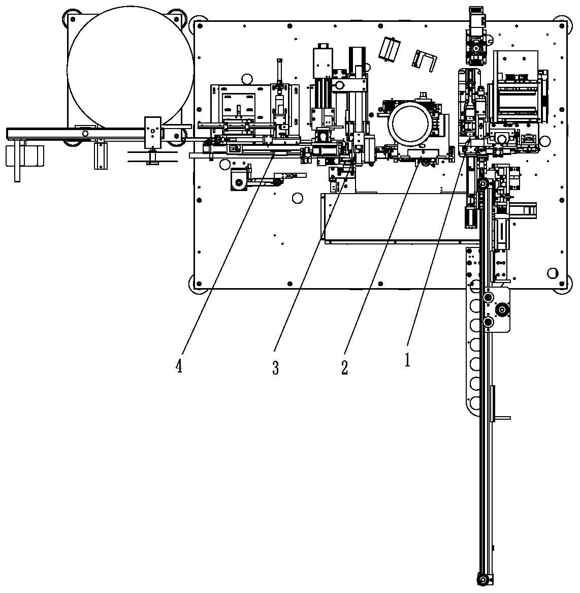
[0045] Please refer to Figures 1 to 3 ,as well as, Figures 20 to 23 As shown, it shows the design structure of the crimping device and the crimping method:

[0046] The end-feeding device 30 is a bottom-feeding type en...


PUM


Abstract

The invention discloses a flexible circuit board full-automatic wire stripping, terminal pressing and shell insertion method and device. The method comprises a wire stripping step, a terminal pressingstep, a branching step and a shell insertion step. The shell insertion step comprises pre-shell insertion and two times of shell insertion. According to the pre-shell insertion, a flexible circuit board terminal is pre-positioned in a plastic shell. The two times of shell insertion comprises first soft insertion and second hard insertion. After the two times of shell insertion is carried out, theflexible circuit board terminal is inserted in place within the plastic shell. A second flexible circuit board clip clamps the flexible circuit board and is rotated outwards, thereby blanking the shell inserted flexible circuit board. A series of flexible circuit board full-automatic wire stripping, terminal pressing and shell insertion actions are realized. In particular, through the pre-shell insertion, the flexible circuit board terminal is guaranteed to be pre-positioned well in the plastic shell. Follow-up shell insertion steps are guaranteed to be carried out successfully. In a follow-up two-time insertion mode, the shell insertion precision is further ensured, the flexible circuit board terminal and/or the plastic shell is prevented from being damaged, a shell insertion reject ratio is reduced, and flexible circuit board terminal shell insertion assembly quality is improved.

Description

technical field [0001] The invention relates to the technology in the field of cable production and processing, in particular to a method for fully automatic cable stripping and crimping end-inserting casings and equipment thereof. Background technique [0002] At present, the cable has been widely used in the signal transmission or power connection of computers, household appliances, communication equipment, and digital equipment. Connectors at the end of the wire to facilitate the plug-in connection between the cable and electronic equipment or electronic components. [0003] In the factory or initial state, the flat wires are combined with multiple wires. When connecting these wires to equipment or terminals (soldering or riveting), the wires need to be separated. At present, most of the thread splitting methods are manual thread splitting, such as cutting with scissors. This method is inefficient and easily cuts the thread; Branching, but these automatic branching devi...

Claims


Application Information

Patent Timeline
IPC IPC(8): H01R43/20H01R43/055H01R43/05
CPCH01R43/05H01R43/055H01R43/20
Inventor 林应听杜昌发姚何郅进男李金华龙智辉
Owner 东莞市超日自动化设备科技有限公司
Why Eureka
Try Eureka