


Quick Research
Generate reliable direction feasibility study reports for your R&D in just a few steps.

Technical Q&A
Discover and master advanced knowledge NOW. Basics, ideas, possibilities, all at once.

Find Solutions
As an expert in R&D theories, this can generate solutions to your technical problems instantly.

Evaluate Feasibility
Analyze your overall solution with one click, know your potential R&D risks in advance.

Monitor Landscape
Get weekly tech updates, stay abreast of the latest tech innovations and key insights.
Infrared laser projection device containing safety monitoring function
An infrared laser, safety monitoring technology, applied in laser parts, lasers, semiconductor lasers, etc., can solve problems such as internal device damage, and achieve the effect of improving sensitivity
- Summary
- Abstract
- Description
- Claims
- Application Information
AI Technical Summary
Problems solved by technology
Method used
Image

Examples
Embodiment 1
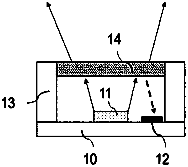
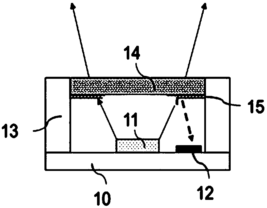
[0027] Such as figure 1 , 2 As shown, an infrared laser projection device with a safety monitoring function includes a base 10, a light source 11, an infrared induction receiver 12, a lens barrel 13, a dodging sheet 14, and a reflective film 15. The light source 11 is fixed on the base 10 , used to generate light beams; the infrared induction receiving device 12 is fixed on the base 10 for receiving the infrared beam reflected by the infrared laser to generate current; the lens barrel 13 is fixed on the base 10 for blocking ambient light and fixing Place the dodging sheet 14, the dodging sheet 14 is fixed on the lens barrel 13, and is used to emit the light beam generated by the light source 11 uniformly out of the device, and the reflective film 15 is fixed on the surface of the dodging sheet 14 facing the wafer, the position Located around the dodging sheet 14. When the light beam passes through the uniform sheet 14 or the reflective film 15, it will be partially reflected...
Embodiment 2
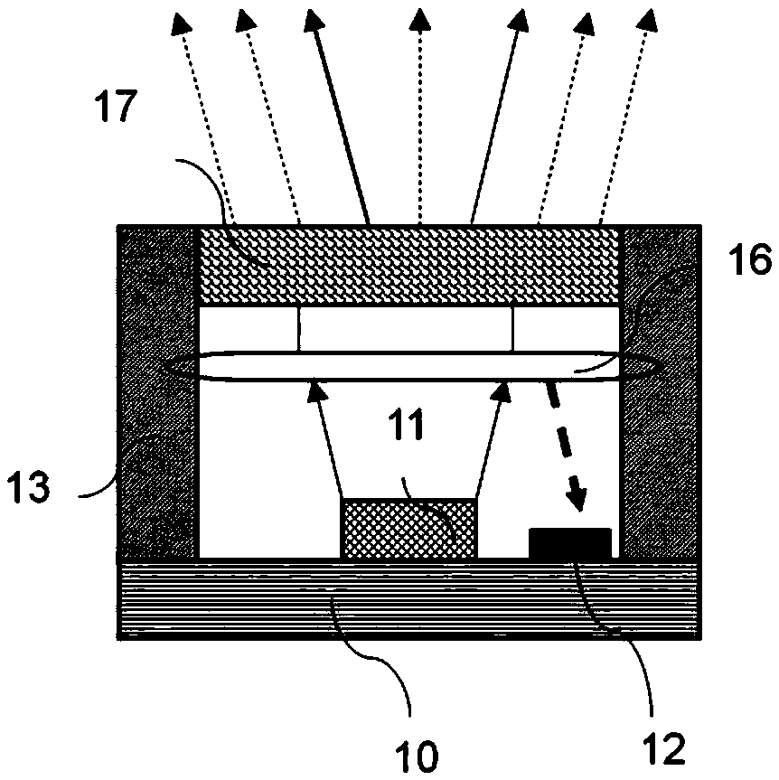
[0034] Such as image 3 , 4 As shown, an infrared laser projection device with a safety monitoring function includes a base 10, a light source 11, an infrared induction receiver 12, a lens barrel 13, an optical diffraction element 17, and a reflective film 15. The light source 11 is fixed on the base 10 , used to generate light beams; the infrared induction receiving device 12 is fixed on the base 10 for receiving the infrared beam reflected by the infrared laser to generate current; the lens barrel 13 is fixed on the base 10 for blocking ambient light and fixing An optical diffraction element 17 is arranged, and the optical diffraction element 17 is fixed on the lens barrel 13, and is used for emitting the light beam that the light source 11 takes place uniformly out of the device, and a collimating lens 16 is arranged below the optical diffraction element 17, for receiving and Converging the light beam generated by the light source 11 , the reflective film 15 is fixed on th...
PUM
| Property | Measurement | Unit |
|---|---|---|
| Thickness | aaaaa | aaaaa |
Abstract
Description
Claims
Application Information
 - R&D Engineer
- R&D Manager
- IP Professional
- Industry Leading Data Capabilities
- Powerful AI technology
- Patent DNA Extraction
Browse by: Latest US Patents, China's latest patents, Technical Efficacy Thesaurus, Application Domain, Technology Topic, Popular Technical Reports.
© 2024 PatSnap. All rights reserved.Legal|Privacy policy|Modern Slavery Act Transparency Statement|Sitemap|About US| Contact US: help@patsnap.com