
Concrete pouring device used for building construction and construction method of concrete pouring device for building construction

A construction and concrete technology, which is applied in the direction of mold fixtures, manufacturing tools, auxiliary molding equipment, etc., can solve the problems of reducing concrete pouring efficiency, affecting concrete pouring quality, and low construction efficiency, so as to improve practicability and flexibility, The effect of improving pouring efficiency and reducing labor intensity

Active Publication Date: 2019-03-12
ZHEJIANG JIETEYOU POWER MACHINERY
View PDF5 Cites 6 Cited by
  • Summary
  • Abstract
  • Description
  • Claims
  • Application Information

AI Technical Summary

Problems solved by technology

[0003] The concrete pouring construction in the prior art generally adopts formwork prefabrication pouring. When the formwork is not long enough, it usually adopts the splicing method, and the formwork is directly supported by the wooden strips and the soil layer on the side. During continuous pouring, if the concrete pouring If the injection speed is too fast, it is easy to break the formwork directly, which not only causes waste of concrete, but also reduces the efficiency of concrete pouring; at the same time, due to the use of manual compaction and smoothing, the construction efficiency is low, and the construction experience of the construction personnel affects the concrete. Pouring quality, it is considered that there are many factors that interfere

Method used


Image

  • Concrete pouring device used for building construction and construction method of concrete pouring device for building construction
  • Concrete pouring device used for building construction and construction method of concrete pouring device for building construction
  • Concrete pouring device used for building construction and construction method of concrete pouring device for building construction

Examples


Embodiment Construction

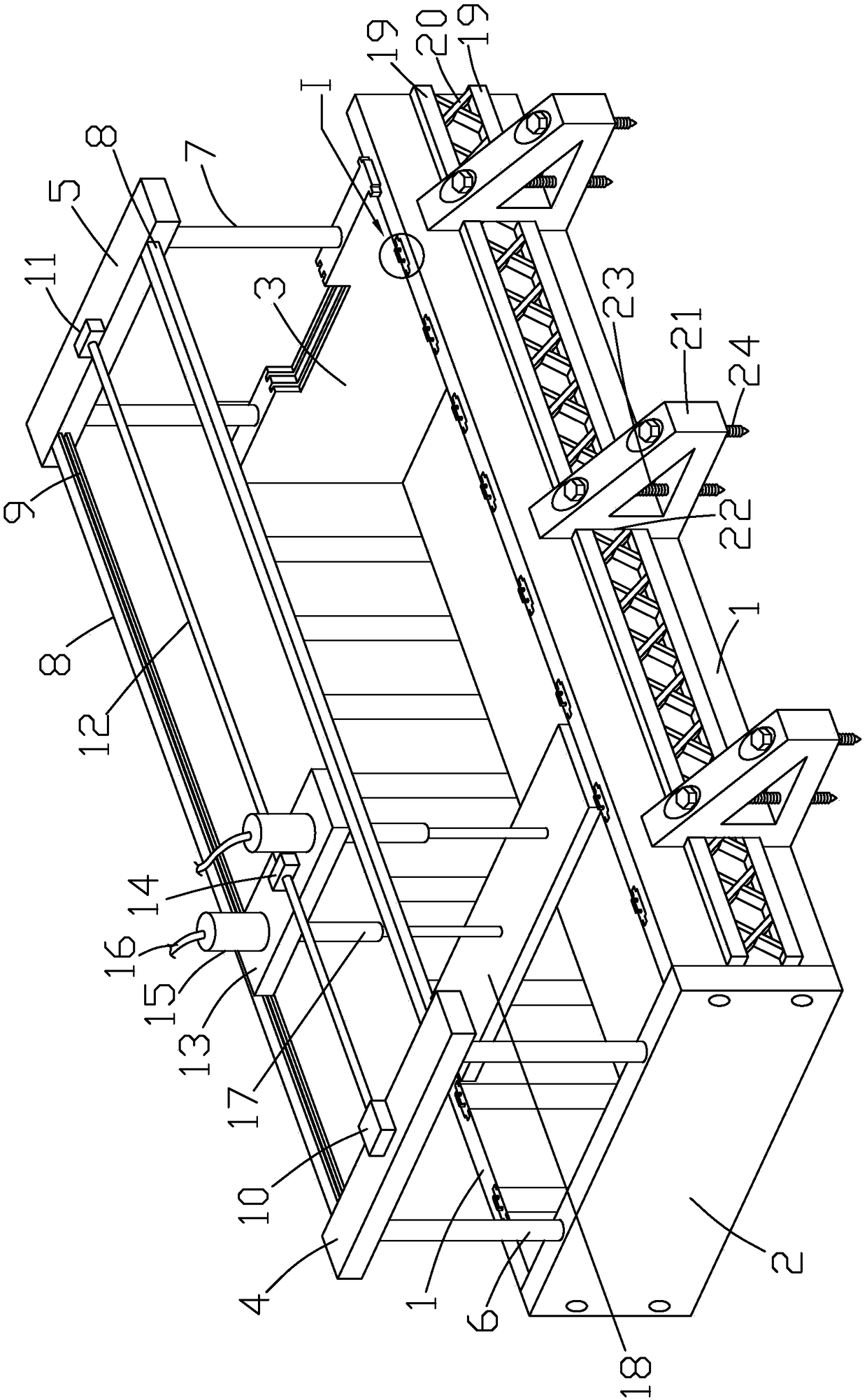
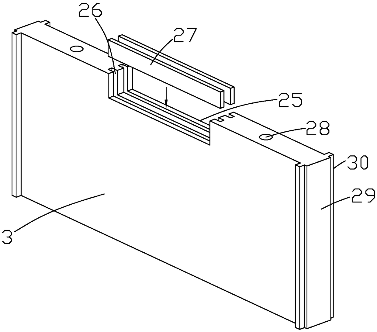
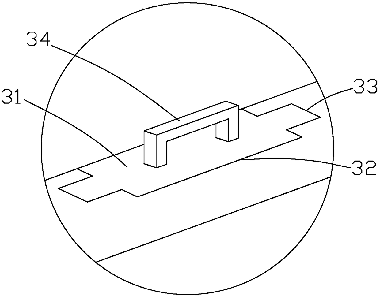
[0043] Such as Figure 1 to Figure 3 As shown, it is a concrete pouring device for building construction of the present invention, which includes a side plate 1, a sealing plate 2, a baffle plate 3, a horizontal movement mechanism and a pouring and compacting mechanism. The two side plates 1 are arranged parallel to each other, and the sealing plate 2 is fixed. Connected to the ends of the two side plates 1, vertical buckle grooves 32 are arranged at equal intervals on the inner side of the side plate 1, horizontal buckle grooves 33 are symmetrically arranged on the left and right sides of the vertical buckle groove 32, and vertical buckle grooves 32 Seal block 31 is all installed in and horizontal buckle groove 33, and seal block 31 is provided with second vertical buckle block and second horizontal buckle block, and the second vertical buckle block matches with vertical buckle groove 32, and the second horizontal buckle block matches. The buckle matches the horizontal buckle...


PUM


Abstract

The invention discloses a concrete pouring device used for building construction and a construction method of the concrete pouring device for building construction. The concrete pouring device comprises side plates, sealing plates, baffles, a horizontal moving mechanism and a casting compaction mechanism. The sealing plates are fixedly connected to the end portions of the two side plates, and vertical buckling grooves are formed in the inner side faces of the side plates at equal intervals. Each baffle is arranged between the corresponding two adjacent vertical buckling grooves. A strengthening mechanism is arranged on the outer side face of each side plate. The horizontal moving mechanism is located between a first cross beam and a second cross beam. The first cross beam and the second cross beam are connected with the sealing plates and the baffles through first supporting pillars and second supporting pillars. The casting compaction mechanism is connected to the horizontal moving mechanism. The construction method includes the steps of survey setting out, side plate and strengthening mechanism installation, sealing plate and baffle installation, horizontal moving mechanism installation, casting compaction mechanism installation and concrete casting. By means of the construction method, steps are simple, practicability is high, the casting efficiency of concrete is improved,the casting quality is improved, and in addition, the labor intensity of manual operation is greatly reduced.

Description

technical field [0001] The invention relates to a concrete pouring device for building construction and a construction method thereof. Background technique [0002] Concrete pouring is a continuous pouring method during construction. [0003] Concrete pouring construction in the prior art generally adopts prefabricated formwork. When the formwork is not long enough, splicing is usually used, and the formwork is directly supported by wooden strips and side soil layers. During continuous pouring, if the concrete pouring If the injection speed is too fast, it is easy to break the formwork directly, which not only causes waste of concrete, but also reduces the efficiency of concrete pouring; at the same time, due to the use of manual compaction and smoothing, the construction efficiency is low, and the construction experience of the construction personnel affects the concrete. Pouring quality, it is considered that there are many factors that interfere. Contents of the invent...

Claims


Application Information

Patent Timeline
IPC IPC(8): B28B7/02B28B7/00B28B3/04B28B17/00
CPCB28B3/04B28B7/0002B28B7/0014B28B7/0097B28B7/02B28B17/00
Inventor 郑君华金波
Owner ZHEJIANG JIETEYOU POWER MACHINERY
Learn More