Supercharge Your Innovation With Domain-Expert AI Agents!

Cable tunnel temperature monitoring system based on distributed optical fiber temperature measuring method

A technology of distributed optical fiber and cable tunnel, which is applied to thermometers, thermometers, measuring devices and other directions with physical/chemical changes, which can solve the influence of measurement accuracy and speed, the inability to accurately measure and locate temperature, and the difficulty of multi-point distribution of temperature field. Measurement and other issues to achieve the effect of reducing losses

Inactive Publication Date: 2019-03-12
长园深瑞继保自动化有限公司
View PDF5 Cites 11 Cited by
  • Summary
  • Abstract
  • Description
  • Claims
  • Application Information

AI Technical Summary

Problems solved by technology

The single-point temperature sensor measures a certain point in the temperature field, which has high measurement accuracy and reliability, but it is difficult to measure the multi-point distribution of the temperature field
In order to solve the measurement problem of multi-point distribution of the temperature field, a quasi-distributed optical fiber temperature sensor composed of a multiplexed optical fiber temperature sensor and an array of optical fiber temperature sensors has emerged. The quasi-distributed optical fiber temperature sensor uses a single-point optical fiber sensor array to form a spatial network distribution. To achieve distributed optical fiber temperature measurement, measurement accuracy and speed will be affected due to resolution, bandwidth or spatial structure, and accurate temperature measurement and positioning cannot be performed

Method used


Image

  • Cable tunnel temperature monitoring system based on distributed optical fiber temperature measuring method
  • Cable tunnel temperature monitoring system based on distributed optical fiber temperature measuring method
  • Cable tunnel temperature monitoring system based on distributed optical fiber temperature measuring method

Examples


Embodiment Construction

[0037] The present invention will be described in further detail below in conjunction with the accompanying drawings and embodiments.

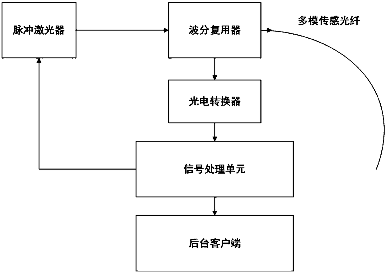
[0038] Such as figure 1 As shown, the cable tunnel temperature monitoring system (temperature monitoring system) based on the distributed optical fiber temperature measurement method of the present invention is provided with sequentially connected pulse lasers, wavelength division multiplexers, photoelectric converters, signal processing units and background clients , the wavelength division multiplexer is connected with a multimode sensing fiber (optical fiber), and the signal processing unit is connected with a pulse laser.

[0039] The pulsed laser generates pulsed laser according to the periodic level signal sent by the signal processing unit, and sends the pulsed laser to the wavelength division multiplexer.

[0040] The center wavelength of the pulsed laser is 1550nm, the peak power is 20mW, the pulse width is 10ns, and the repetition f...


PUM

PropertyMeasurementUnit
Center wavelengthaaaaaaaaaa
Peak poweraaaaaaaaaa
Pulse widthaaaaaaaaaa

Abstract

The invention discloses a cable tunnel temperature monitoring system based on a distributed optical fiber temperature measuring method. The system aims at solving the technical problem about how to accurately monitor the temperature distribution condition of a cable tunnel in real time. By the adoption of the technical scheme, the cable tunnel temperature monitoring system based on the distributedoptical fiber temperature measuring method is provided with a pulse laser, a wavelength division multiplexer, a photoelectric converter and a signal processing unit, wherein the pulse laser, the wavelength division multiplexer, the photoelectric converter and the signal processing unit are sequentially connected, and the wavelength division multiplexer is connected with a multi-mode sensing optical fiber. Compared with the prior art, optical fiber temperature distributed information of the cable tunnel is extracted through Raman scattered light signals, the temperature distribution conditionof the cable tunnel can be accurately monitored in real time, the status of the cable tunnel can be known in real time by maintenance staff, fault hidden danger can be predicted before occurring, probably-existing faults can be processed in time, and therefore losses are reduced.

Description

technical field [0001] The invention relates to the field of temperature monitoring of a power system, in particular to a cable tunnel temperature monitoring system. technical background [0002] The smart grid of the power system includes power plants, high-voltage power grids, substations, distribution stations, etc., specifically including power equipment such as generators, transformers, power cables, and switches. Power equipment usually works in high voltage, strong electric field, heat load and other environments, and the working environment is unattended and unmanned. As an engineering infrastructure, the smart grid involves the electricity demand of thousands of households. The operating temperature of power equipment is an important factor to ensure the safe operation of the smart grid. Whether it is a transformer, a power cable, or other power equipment, as an important part of the power system, some circuit problems or external factors may cause local overheatin...

Claims


Application Information

Patent Timeline
IPC IPC(8): G01K11/32G01K11/324
CPCG01K11/32G01K11/324
Inventor 陈锐徐盛果袁列荣陶树建张松琛陈科祥
Owner 长园深瑞继保自动化有限公司
Features
  • R&D
  • Intellectual Property
  • Life Sciences
  • Materials
  • Tech Scout
  • Unparalleled Data Quality
  • Higher Quality Content
  • 60% Fewer Hallucinations
Learn More