
Novel microgrid fault current limiting method

A current-limiting method and micro-grid technology, applied in AC network circuits, single-network parallel feeding arrangements, emergency protection circuit devices for limiting overcurrent/overvoltage, etc., can solve large fault currents, fault current changes, etc. problem, to achieve the effect of fast response and small current peak value

Active Publication Date: 2019-03-12
SHANGHAI UNIVERSITY OF ELECTRIC POWER
View PDF6 Cites 1 Cited by
  • Summary
  • Abstract
  • Description
  • Claims
  • Application Information

AI Technical Summary

Problems solved by technology

[0006] The purpose of the present invention is to provide a theoretically advanced and unaffected new microgrid fault current limiting method in order to solve the two problems of large fault current and fault current changing with fault type

Method used


Image

  • Novel microgrid fault current limiting method
  • Novel microgrid fault current limiting method
  • Novel microgrid fault current limiting method

Examples


Embodiment

[0043] 1. Microgrid structure and its voltage and current double loop controller

[0044] (1) Microgrid structure

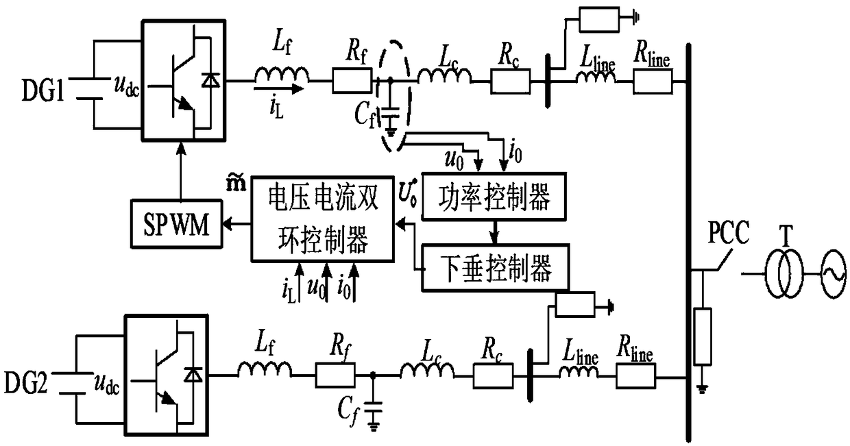
[0045] figure 1 It is the structure and control system of the microgrid of the present invention. In the figure, there are two voltage source inverters DG1 and DG2 in the microgrid, and they are all controlled by droop; L f , R f and C f Inductance, resistance and capacitance for filtering; L c , R c is the coupled inductance and resistance; L line , R line Inductance and resistance of the line; loads 1 to 3 are constant power loads; u 0 i 0 It is the voltage and current output by DG, and its rated value is u E i E ; is the reference value of the output voltage; i L is the filter inductor current; u dc is the DC side voltage.

[0046] (2) Voltage and current double loop controller

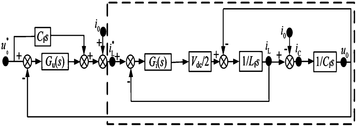
[0047] PI control has problems such as AC steady-state error and poor anti-interference ability. Proportional resonance (PR) control can solve this problem, and can d...


PUM


Abstract

The invention relates to a novel microgrid fault current limiting method. The method comprises the following steps: step 1, according to a voltage-current dual-loop proportional resonance (PR) controller model of a distributed generator (DG) converter controlled by loop, deriving and obtaining a reference value of a filtering inductance current and the relation between the current and the voltageoutput by a DG unit; step 2, setting filtering capacitance and a voltage-current dual-loop PR controller parameter and enabling the output current of the DG unit to track the reference value of the filtering inductance current; step 3, setting a current limiting threshold value, and when the effective value of a certain phase current in the output current of the DG unit is larger than the currentlimiting threshold value, carrying out current limiting by changing the reference value of the filtering inductance current of a current inner ring in the voltage-current PR dual-loop controller. Compared with the prior art, the fault current can be limited to be near double a current rated value in the invention; and the method has the advantages of not being affected by the short circuit type, the fault resistance and the fault moment.

Description

technical field [0001] The invention relates to the technical field of relay protection for micro-grids, in particular to a novel current limiting method for micro-grid faults. Background technique [0002] As the penetration rate of Distributed Generator (DG) increases, more and more DGs are connected in the form of micro-grids, and the DGs of micro-grids are mostly power electronic devices, and their overcurrent capability is limited. , in order to protect the relevant power electronic devices in the microgrid from being damaged by short-circuit current and improve the power quality output by the microgrid during a fault, it is of great significance to study the current limiting capability of the microgrid. [0003] For the microgrid current limiting strategy, using a fault current limiter (Fault Current Limiter, FCL) is a common method. Although FCL has good current-limiting performance, its equipment is complex and expensive. Therefore, many literatures study current-li...

Claims


Application Information

Patent Timeline
IPC IPC(8): H02J3/38H02H9/02
CPCH02J3/383H02H9/02H02J3/381Y02E10/56
Inventor 程启明程尹曼魏霖王玉娇沈磊
Owner SHANGHAI UNIVERSITY OF ELECTRIC POWER
Learn More