Thermal expansion amount control method of numerical control flame cutting steel plate part sizes

A technology of flame cutting and thermal expansion, which is applied in the direction of gas flame welding equipment, manufacturing tools, welding equipment, etc., can solve the problems of restricting the dimensional accuracy and production efficiency of CNC flame cutting, not allowing multiple trial cutting, and large size deviation of parts , to achieve the effect of eliminating adverse effects, stable and reliable dimensional accuracy, and small dimensional deviation

Inactive Publication Date: 2019-03-15
YUNNAN HEAVY EQUIP MFG GRP
View PDF3 Cites 3 Cited by
  • Summary
  • Abstract
  • Description
  • Claims
  • Application Information

AI Technical Summary

Problems solved by technology

[0005] At present, for the dimensional deviation caused by the thermal expansion in the CNC flame cutting process, a certain amount of thermal expansion compensation △t is generally added to the kerf compensation K based on experience, and there is no feasible theoretical guidance
Due to the limitations of everyone's experience, the value of the thermal expansion compensation △t often leads to large dimensional deviation and instability of the cut parts. Generally, multiple trial cuts and adjustments are required to achieve the predetermined accuracy. Not only the cutting efficiency is low, but also Trial cutting costs are high, and multiple trial cuttings are not allowed for small batches and high-value plates, which greatly restricts the dimensional accuracy and production efficiency of CNC flame cutting

Method used


Image

  • Thermal expansion amount control method of numerical control flame cutting steel plate part sizes
  • Thermal expansion amount control method of numerical control flame cutting steel plate part sizes

Examples


Embodiment

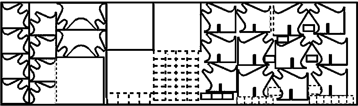
[0034] The steel plates of 4 sets of 85 tons ladles are cut by conventional CNC flame cutting, such as figure 1 For the discharge of the steel plate parts shown, when the thermal expansion △t is not added to the slot compensation K, due to the small size of the parts, the large number, and the intensive discharge, a large amount of heat is input into the steel plate during cutting, and the dotted line in the figure is due to thermal expansion. Dimensional deviations occur after the parts cool down. The specific parameters are as follows:

[0035] The weight of the blanking part is: 139.31 tons, the pass rate of the blanking is: 95%, the average price of the plate: 5000 yuan / ton, the labor wage: 332 yuan / day / person, the daily consumption: 120 yuan / ton, the scrap steel price: 2500 yuan / Ton.

[0036] The resulting damage is calculated as follows:

[0037] The size does not match the weight: 139.31 tons × 5% = 6.96 tons,

[0038] Labor wages: 332×6.96×2=2312 yuan,

[0039] D...


PUM


Abstract

The invention discloses a thermal expansion amount control method of numerical control flame cutting steel plate part sizes. The method includes the steps that the long and short diameter ratio is calculated according to the sizes of pre-cut formed parts; the average temperature T1 of steel plates corresponding to the parts during cutting is estimated according to the thicknesses of the steel plates and the sizes and the shapes of the parts, and the cutting temperature difference delta T=T1-room temperature is calculated; and thermal expansion compensation amounts are calculated, wherein the unilateral thermal expansion compensation amount delta t is added to the kerf compensation K of the parts with the long and short diameter ratio of 1.0-1.3, the unilateral thermal expansion compensation amount delta t1 is added to the short-diameter direction kerf compensation K1 of the parts with the long and short diameter ratio not smaller than 1.2-1.3, and the unilateral thermal expansion compensation amount delta t2 is added to the long-diameter direction kerf compensation K2 of the parts with the long and short diameter ratio not smaller than 1.2-1.3. The corresponding thermal expansion compensation amounts are added to kerfs according to part temperature rise and the long and short diameter ratio, and therefore bad influences of thermal expansion of numerical control flame cutting onthe part sizes are eliminated.

Description

technical field [0001] The invention belongs to the technical field of numerical control flame cutting, and in particular relates to a method for controlling thermal expansion of the size of numerical control flame cutting steel plate parts with simple control method, small and stable size deviation of cutting parts and high cutting efficiency. Background technique [0002] Flame cutting (Flame Cutting) uses the high temperature generated by the combustion of acetylene, propane, natural gas and other flammable gases to cut steel plates. In the field of steel plate flame cutting, with the development of science and technology, high-precision, easy-to-control, high-efficiency semi-automatic flame cutting and CNC flame cutting have been widely used. [0003] However, in the actual CNC flame cutting process, the cutting ignition temperature reaches 1100-1150°C, and the cutting parts on the entire steel plate come first and then later. The temperature of the steel plate is close...

Claims


Application Information

Patent Timeline
IPC IPC(8): B23K7/10B23K7/00
CPCB23K7/003B23K7/10
Inventor 周建侠刘雨代志梅
Owner YUNNAN HEAVY EQUIP MFG GRP
Why Eureka
Try Eureka