Eureka AIR delivers breakthrough ideas for toughest innovation challenges, trusted by R&D personnel around the world.

Brake energy distribution method based on dynamic quality estimation of electric bus

An electric bus, mass estimation technology, applied in electric vehicles, electric braking systems, drive interaction and other directions, can solve the problems of low accuracy of braking residual energy evaluation and poor braking energy recovery efficiency, and achieve accurate real-time kinetic energy, The effect of improving recycling efficiency

Active Publication Date: 2019-03-15
HARBIN UNIV OF SCI & TECH
View PDF5 Cites 2 Cited by
  • Summary
  • Abstract
  • Description
  • Claims
  • Application Information

AI Technical Summary

Problems solved by technology

[0004] The present invention aims to solve the problem of low accuracy of braking remaining energy evaluation and poor braking energy recovery efficiency due to the influence of the real-time quality of the electric passenger car on the recyclable braking energy during the braking energy recovery process of the existing electric passenger car problem, a braking energy distribution method based on dynamic mass estimation for electric buses is proposed

Method used


Image

  • Brake energy distribution method based on dynamic quality estimation of electric bus
  • Brake energy distribution method based on dynamic quality estimation of electric bus
  • Brake energy distribution method based on dynamic quality estimation of electric bus

Examples


specific Embodiment approach 1

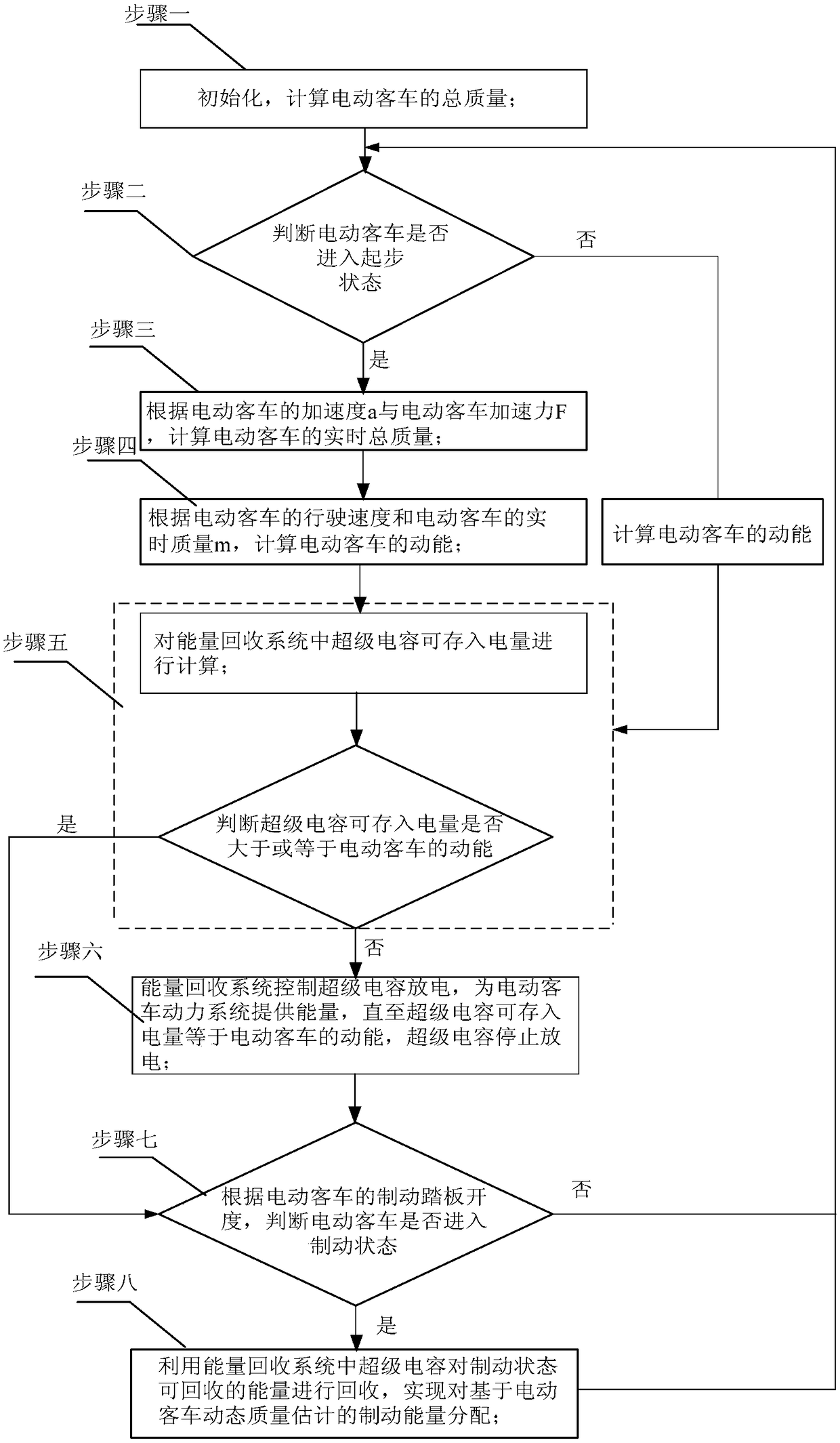
[0029] Specific implementation mode one: the following combination figure 1 Describe this embodiment, the brake energy distribution method based on the dynamic mass estimation of electric passenger car described in this embodiment, the specific steps of this method are:

[0030] Step 1. Initialize and calculate the total mass of the electric bus;

[0031] Step 2. According to the speed and acceleration signals of the electric bus, it is judged whether the electric bus has entered the starting state; if so, then perform step 2; otherwise, calculate the kinetic energy of the electric bus and perform step 5;

[0032] Step 3, according to the acceleration a of the electric bus and the acceleration force F of the electric bus, calculate the real-time total mass of the electric bus; and automatically update the real-time total mass of the electric bus;

[0033] Step 4, calculate the kinetic energy of the electric bus according to the driving speed of the electric bus and the real-t...

specific Embodiment approach 2

[0039] Specific embodiment two: This embodiment further explains the braking energy distribution method based on the dynamic mass estimation of the electric passenger car described in the first embodiment. In step one, the specific method for calculating the total mass of the electric passenger car is:

[0040] Step 11, using a torque sensor to collect the motor torque T of the electric bus; and calculating the acceleration force F of the electric bus in combination with the wheel radius r of the electric bus;

[0041] Step 12: Calculate the real-time total mass of the electric bus according to the calculated acceleration force F of the electric bus and the acceleration a of the electric bus measured by the acceleration sensor.

specific Embodiment approach 3

[0042] Specific embodiment three: this embodiment further explains the braking energy distribution method based on the dynamic mass estimation of the electric passenger car described in the second embodiment, the calculation of the acceleration force F of the electric passenger car in step one and the acceleration force F of the electric passenger car in step three The method is the same, both through the formula:

[0043] F=T / r (1)

[0044] Calculated to get.


PUM


Abstract

The invention discloses a brake energy distribution method based on dynamic quality estimation of an electric bus, belongs to the field of brake energy distribution of electric buses, and solves the problems of low accuracy rate of brake residual energy evaluation and poor brake energy recovery efficiency caused by the influence of the real-time quality of a prior electric bus on recoverable brakeenergy in the brake energy recovery process of the bus. According to the invention, an acceleration sensor device and a torque sensor device are additionally arranged in the composite energy storageelectric bus, in the initial acceleration stage of the electric bus, the acceleration force of the electric bus is calculated through the measured output torque of a motor and the radius of a wheel, and calculation is carried out to obtain the real-time mass m of the electric bus. And the real-time kinetic energy of the electric bus is calculated by using the speed and mass of the electric bus soas to determine the recoverable maximum energy. The remaining charging capacity of a super capacitor is reserved according to the maximum energy that can be recovered when braking. The method is suitable for the use of electric buses.

Description

technical field [0001] The invention belongs to the field of braking energy distribution of electric passenger cars, and in particular relates to a braking energy distribution method. Background technique [0002] With the intensification of the oil crisis and environmental pollution, electric vehicles have become the main development direction of ground transportation in the future. Vehicles running on urban road conditions must frequently accelerate and brake due to traffic congestion. Traditional internal combustion engine vehicles convert braking energy into heat energy through the brakes in the form of friction and lose it, while hybrid electric vehicles play the regenerative braking function of the motor. , which can recover the kinetic energy of the vehicle during braking, which can significantly improve fuel economy and reduce emissions when driving in urban conditions. [0003] At present, for the problem of braking energy distribution of hybrid energy storage elec...

Claims


Application Information

Patent Timeline
Patent Type & Authority Applications(China)
IPC IPC(8): B60L7/10
CPCB60L7/10B60L2240/16B60L2240/26B60L2240/423B60L2240/46B60L2250/26
Inventor 吴晓刚刘野
Owner HARBIN UNIV OF SCI & TECH
Why Eureka
Eureka Blog
Learn More