
Once turning and milling combined cutting device

A cutting device, a one-time technology, applied to other manufacturing equipment/tools, manufacturing tools, etc., can solve the problems that affect the processing quality and efficiency of parts, the number of repeated clamping of workpieces, and the poor positioning accuracy of tool holders, etc., to improve Production efficiency, improvement of equipment processing range, and stable product quality

Inactive Publication Date: 2019-03-19
中设精工制造江苏有限公司
View PDF0 Cites 0 Cited by
  • Summary
  • Abstract
  • Description
  • Claims
  • Application Information

AI Technical Summary

Problems solved by technology

[0002] Generally, only 4 knives can be installed on the traditional CNC tool post. For the processing of long copper sleeve parts with inner oil groove, it is often necessary to pull the oil groove after the outer circle and inner hole. Unstable product quality and low efficiency
[0003] For the above processing method, when the precision of the inner groove, outer circle and inner hole is required for the part, relying entirely on the alignment of the part will affect the processing quality and efficiency of the part

Method used


Image

  • Once turning and milling combined cutting device
  • Once turning and milling combined cutting device
  • Once turning and milling combined cutting device

Examples


Embodiment Construction

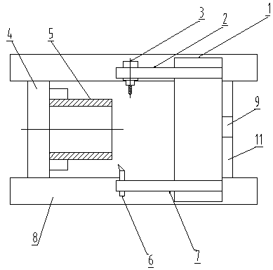
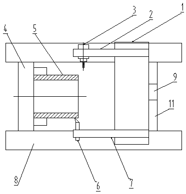
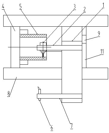
[0018] The present invention includes a carriage 8 in a lathe, and a support plate 1 that moves forward and backward along the carriage 8 in the lathe is provided on the carriage 8 in the lathe;

[0019] The support plate 1 is provided with a power milling head tool holder 2 and a turning tool tool holder 7 that can move left and right along the support plate 1, a power milling head 3 is installed on the power milling head tool holder 2, and the turning tool tool Turning tool 6 is installed on the frame 7;

[0020] A fixture 4 for installing a workpiece 5 is fixedly arranged on the carriage 8 in the lathe, and the workpiece 5 is arranged opposite to the power milling head 3 and the turning tool 6 .

[0021] The turning tool holder 7 and the milling head tool holder 2 are segmented structures, including a heavy rod and a light rod connected together, the heavy rod is connected on the support plate 1, and the light rod is used to set the power milling rod. Head 3 and turning to...


PUM


Abstract

The invention relates to an once turning and milling combined cutting device. The device comprises a lathe middle carriage (8); a support plate (1) capable of moving front and back along the lathe middle carriage (8) is arranged on the lathe middle carriage (8); a power milling head cutter frame (2) and a turning cutter frame (7) capable of moving left and right along the support plate (1) are arranged on the support plate (1); a power milling head (3) is mounted on the power milling head cutter frame (2); a turning cutter (6) is mounted on the turning cutter frame (7); a fixture (4) for mounting workpieces (5) is fixedly arranged on the lathe middle carriage (8); and the workpieces (5) are arranged on opposite surfaces of the power milling head (3) and the turning cutter (6). The device applies a double-row cutter frame machining process to once finish the machining of part outer circles, inner holes and oil tanks, widens the equipment machining range, reduces repetition of cutters, achieves stable product quality, and meanwhile, greatly improves the production efficiency.

Description

technical field [0001] The invention relates to the transformation of a numerical control tool holder, which is applied to the processing technology of adding a supporting double-row tool holder on a numerical control carriage. Background technique [0002] Generally, only 4 knives can be installed on the traditional CNC tool post. For the processing of long copper sleeve parts with inner oil groove, it is often necessary to pull the oil groove after the outer circle and inner hole. The product quality is unstable and the efficiency is low. [0003] For the above-mentioned processing methods, when the precision of the inner groove, outer circle and inner hole is required for the parts, completely relying on the alignment of the parts will affect the processing quality and efficiency of the parts. Contents of the invention [0004] The present invention aims at above-mentioned defects, and the purpose is to provide a double-row tool post processing technology that can comp...

Claims


Application Information

Patent Timeline
IPC IPC(8): B23P23/04
CPCB23P23/04
Inventor 何叶锋
Owner 中设精工制造江苏有限公司
Learn More