Visual positioning method

A technology of visual positioning and positioning holes, applied in the field of visual positioning, can solve the problems of inaccurate positioning of mechanical structures, waste of production beats, time-consuming and other problems, and achieve the effects of improving cycle utilization, high positioning accuracy, and reliable positioning results

Inactive Publication Date: 2019-03-19
施努卡(苏州)智能装备有限公司
View PDF8 Cites 11 Cited by
  • Summary
  • Abstract
  • Description
  • Claims
  • Application Information

AI Technical Summary

Problems solved by technology

[0003] In the prior art, the positioning of the vehicle body is mainly realized by mechanical structures, such as the positioning method of high-speed lifting roller bed, sled and positioning fixture, or the positioning method of high-speed horizontal roller bed plus accompanying fixture, but these use mechanical Structural solutions generally have flexibility limitations (the same production line can only be compatible with the production of several models), waste of production tact (the positioning process involves lifting and lowering of the mechanical structure, which will consume time), high energy consumption (the positioning process Involving the lifting and lowering of the mechanical structure, which will consume some electric energy) and the inaccurate positioning caused by the mutual wear of the mechanical structure in the contact process with the vehicle body, etc.

Method used


Image

  • Visual positioning method
  • Visual positioning method
  • Visual positioning method

Examples


no. 1 example

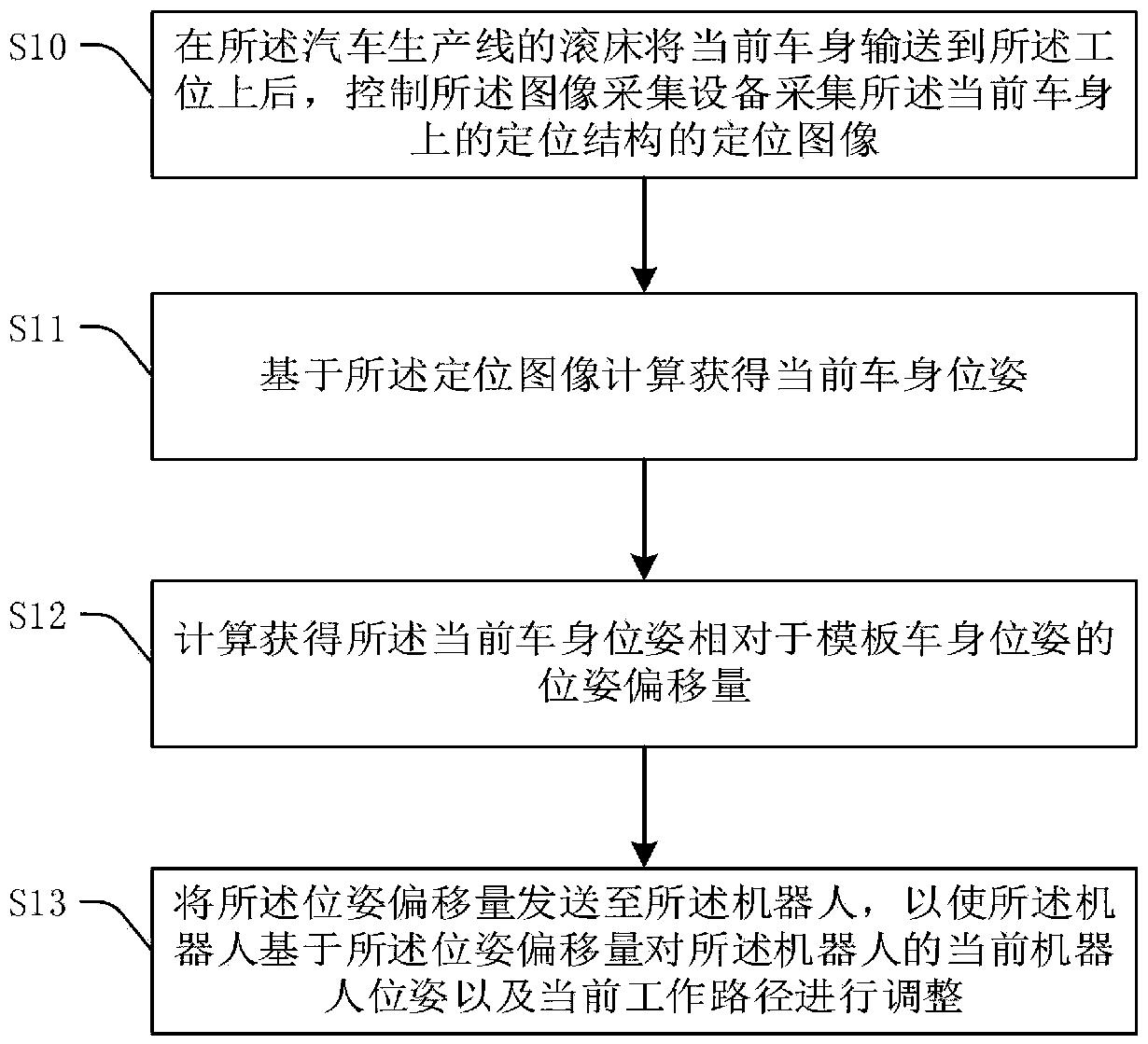
[0035] Refer to attached image 3 , the method includes:

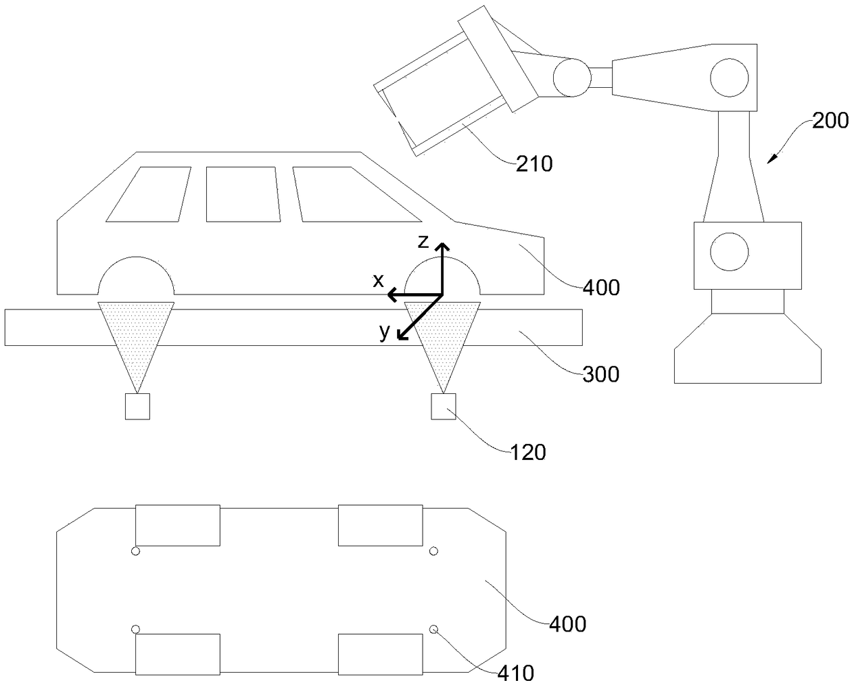
[0036] Step S10 : After the rolling bed 300 of the automobile production line transports the current vehicle body 400 to the station, control the image acquisition device 120 to capture the positioning image of the positioning structure 410 on the current vehicle body 400 .

[0037]After the rolling bed 300 transports the current vehicle body 400 to the work station, the control device 110 controls the image acquisition device 120 arranged under the rolling bed to photograph the positioning structure 410 at the bottom of the current vehicle body 400 to obtain a positioning image of the positioning structure, and The positioning image is sent to the control device 110 . In the embodiment of the present invention, the positioning structure 410 may be a positioning hole at the bottom of the current vehicle body 400, such as an RPS positioning hole. The RPS system was first invented by the Ford Company of the United Stat...

no. 2 example

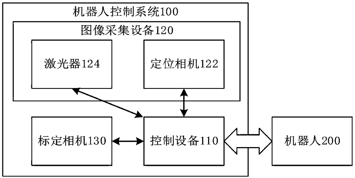
[0058] The robot device 500 is applied to the control device 110 in the visual positioning system 100. The visual positioning system 100 also includes an image acquisition device 120 connected to the control device 110. The visual positioning system 100 is installed on the station of the automobile production line, and the station is provided with The robot 200 communicates with the control device 110 . Refer to attached Figure 7 , the visual positioning device 500 includes: an image acquisition module 510 , a pose acquisition module 520 , an offset acquisition module 530 and a robot control module 540 .

[0059] Wherein, the image acquisition module 510 is used to control the image acquisition 120 equipment to collect the positioning image of the positioning structure on the current vehicle body 400 after the rolling bed 300 of the automobile production line transports the current vehicle body 400 to the station; the pose acquisition module 520 is used to Calculate and obta...


PUM


Abstract

The invention relates to the technical field of automobile manufacturing, in particular to a visual positioning method. The visual positioning method comprises the specific steps that a, a positioningimage of a positioning structure on a current vehicle body is collected; b, equipment is controlled to calculate and obtain a pose of the current vehicle body based on the positioning image; c, the equipment is controlled to calculate and obtain pose offset of the pose of the current vehicle body relative to a pose of a template vehicle body; and d, the equipment is controlled to send the pose offset to a robot to enable the robot to adjust a pose and a current working path of the robot. According to the visual positioning method, a software method is used for controlling the robot to adjustthe pose and the working path, the robot is adapted to the pose of the current vehicle body, and when vehicle bodies of different vehicle models are processed, only related software parameters in thevisual positioning method need to be adjusted correspondingly; and a cycle use ratio in the production process can be improved, the energy consumption is reduced, the mechanical wear problem in an existing technology does not exist, the positioning precision of the robot is high, and the positioning result is reliable.

Description

technical field [0001] The invention relates to the technical field of automobile manufacturing, in particular to a visual positioning method. Background technique [0002] At present, in the automobile manufacturing process, the manufacture of the body is mainly completed by robots installed on the automobile production line. After the rolling bed of the automobile production line transports the current body to the station, the robot, under the control of the built-in program, performs corresponding operations according to the preset work path in the program, such as body assembly, welding, gluing, laser welding, etc. Obviously, under the premise of not changing the built-in program of the robot, it is necessary to ensure that the rolling bed transports the current body to the same position with the same body posture every time, so as to ensure the normal operation of the robot. This process is called localization of the current body. [0003] In the prior art, the positi...

Claims


Application Information

Patent Timeline
Patent Type & Authority Applications(China)
IPC IPC(8): B25J9/16
CPCB25J9/1664B25J9/1697
Inventor 雷金波谭思源汪勇王聪然赵轩张仁钰杨峰
Owner 施努卡(苏州)智能装备有限公司
Why Eureka
Try Eureka