
An ethylene cracking furnace

An ethylene cracking furnace and cracking furnace technology, applied in the directions of cracking, hydrocarbon cracking to hydrocarbon production, non-catalytic thermal cracking, etc. The effect of improving the yield of olefins

Active Publication Date: 2020-11-13
CHINA PETROLEUM & CHEM CORP +1
View PDF2 Cites 1 Cited by
  • Summary
  • Abstract
  • Description
  • Claims
  • Application Information

AI Technical Summary

Problems solved by technology

[0009] The purpose of the present invention is to solve the problem that the ethylene cracking furnace in the prior art has insufficient flexibility across the tubes and the large distance between the two groups of furnace tubes causes uneven heating, resulting in overheating of the furnace tubes and shortening the operating cycle of the cracking furnace The problem is to provide an ethylene cracking furnace, which can not only provide a radiant furnace tube structure, but also provide a cross-tube pipeline with sufficient flexibility to meet the needs of absorbing the thermal expansion of the furnace tube, thereby avoiding the bending of the furnace tube; in addition, it can Avoid the blockage of the furnace tube, which can improve the heat transfer efficiency of the furnace tube

Method used


Image

  • An ethylene cracking furnace
  • An ethylene cracking furnace
  • An ethylene cracking furnace

Examples


Embodiment Construction

[0040] Hereinafter, preferred embodiments of the present invention will be described in more detail with reference to the accompanying drawings. Although the preferred embodiments of the present invention are shown in the drawings, it should be understood that the present invention can be implemented in various forms and should not be limited by the embodiments set forth herein. The present invention will be described in further detail below in conjunction with the accompanying drawings:

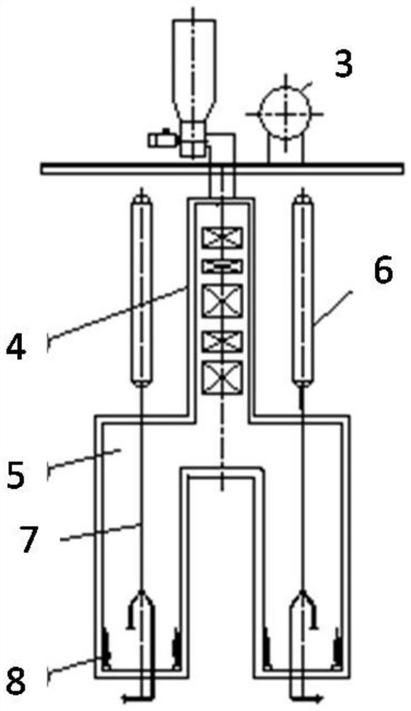
[0041] Such as figure 1 As shown, an ethylene cracking furnace includes: a high-pressure steam drum 3, a convection section 4, a radiant section 5, a quenching boiler 6 and a burner 8;

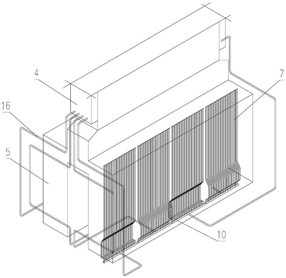
[0042] A single-pass radiant furnace tube 7 is arranged in the radiant section 5, such as figure 2 As shown, the radiant furnace tube 7 includes an outlet section straight pipe 140 and an elbow connecting piece, the elbow connecting piece is composed of two S-shaped elbow pipes 30 and an inlet straight pipe 121 ...


PUM


Abstract

The invention belongs to a petrochemical industry, and provides an ethylene cracking furnace which comprises a high-pressure drum, a convection section, a radiation section, a quenching boiler and a combustor. Single-pass radiation furnace pipes are arranged in the radiation section and comprise inlet section straight pipes and bending pipe connectors, each bending pipe connector comprises two S-shaped bending pipes and an inlet straight pipe positioned between the two S-shaped bending pipes, a plurality of radiation furnace pipes form a large group, a plurality of large groups are arranged inthe radiation section, all radiation furnace pipes in each large group are connected with a shared collecting tube through the bending pipe connectors, outlet section straight pipes of the radiationfurnace pipes in each large group are vertically arranged relative to the bottom of the combustor, the convection section is connected with the collecting tube through a crossover pipe, and the crossover pipe is of a stereoscopic II-type structure distributed along the length, width and height directions of a furnace body of the radiation section. A distributed mode of the crossover pipe can ensure that a line of the crossover pipe has sufficient flexibility to absorb thermal expansion of the furnace pipes, so that bending of the furnace pipes is avoided.

Description

Technical field [0001] The invention belongs to the field of petrochemical industry, and specifically relates to an ethylene cracking furnace. Background technique [0002] In the ethylene plant, the cracking furnace is the core equipment (see figure 1 ). The radiant section of the early cracking furnace was arranged horizontally in the radiant section. With the development of cracking technology, the first double-sided radiant short residence time cracking furnace with a vertical radiant section tube structure was developed in Germany in 1964. Since its launch, several companies engaged in the development of ethylene technology have invested a large amount of capital and technical strength in the development of cracking technology. [0003] In order to shorten the residence time of the cracking reaction as much as possible and increase the cracking depth at the same time, the radiant coil (furnace tube) of the cracking furnace has developed in the direction of short length and sm...

Claims


Application Information

Patent Timeline
Patent Type & Authority Patents(China)
IPC IPC(8): C10G9/20
CPCC07C4/04C10G9/20C07C11/04
Inventor 何细藕邵晨刘克刚李昌力刘敬坤侯瑞陈永亮
Owner CHINA PETROLEUM & CHEM CORP
Learn More