Dust-laden flue gas classification purification waste heat recovery system and dedusting heat storage and exchange device

A waste heat recovery system and heat exchange device technology, applied in indirect heat exchangers, separation methods, gas treatment, etc., can solve the problems of complex production and processing, unfavorable heat transfer, long production cycle, etc., and achieve reasonable structural design and increase Disturbance of flue gas flow, expansion of heat exchange area, and reduction of heat pipe wear

Inactive Publication Date: 2019-03-19
CHONGQING UNIV
View PDF10 Cites 3 Cited by
  • Summary
  • Abstract
  • Description
  • Claims
  • Application Information

AI Technical Summary

Problems solved by technology

The production and processing of the above-mentioned inner tube structure is relatively complicated and the cost is relatively high, while the welding or expansion joint used in the processing of the outer tube fins produces a large contact thermal resistance, which is not conducive to heat transfer. In addition, the cost is high and the production cycle is long. The problem

Method used


Image

  • Dust-laden flue gas classification purification waste heat recovery system and dedusting heat storage and exchange device
  • Dust-laden flue gas classification purification waste heat recovery system and dedusting heat storage and exchange device
  • Dust-laden flue gas classification purification waste heat recovery system and dedusting heat storage and exchange device

Examples


Embodiment 1

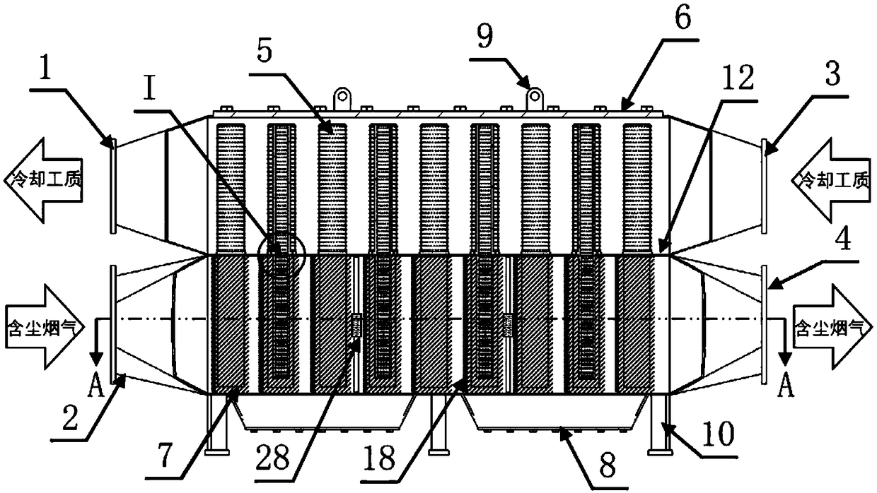
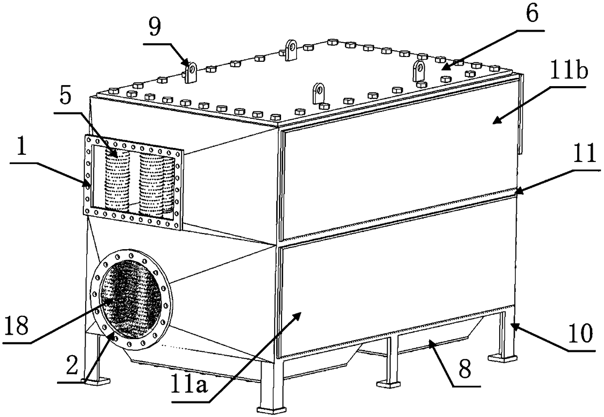
[0033] Embodiment 1: see Figure 1 to Figure 6, a waste heat recovery system for classification and purification of dusty flue gas, comprising a housing 11, the housing 11 is a hollow cuboid structure, a partition 12 is arranged in the middle of the housing 11, and the partition 12 separates the housing 11 into There are two upper and lower chambers, the lower chamber is the flue gas channel 11a, and the upper chamber is the cooling working medium channel 11b; the left end of the flue gas channel 11a is provided with a flue gas inlet 2, and the right end is provided with a flue gas outlet 4, The lower end is provided with a step-shaped dust removal port 8; the left end of the cooling medium channel 11b is provided with a cooling medium outlet 1, and the right end is provided with a first cooling medium inlet 3; Heat exchange device and ash cleaner 28; the dust removal and storage heat exchange device is composed of several dust removal and storage heat exchange units arranged ...

Embodiment 2

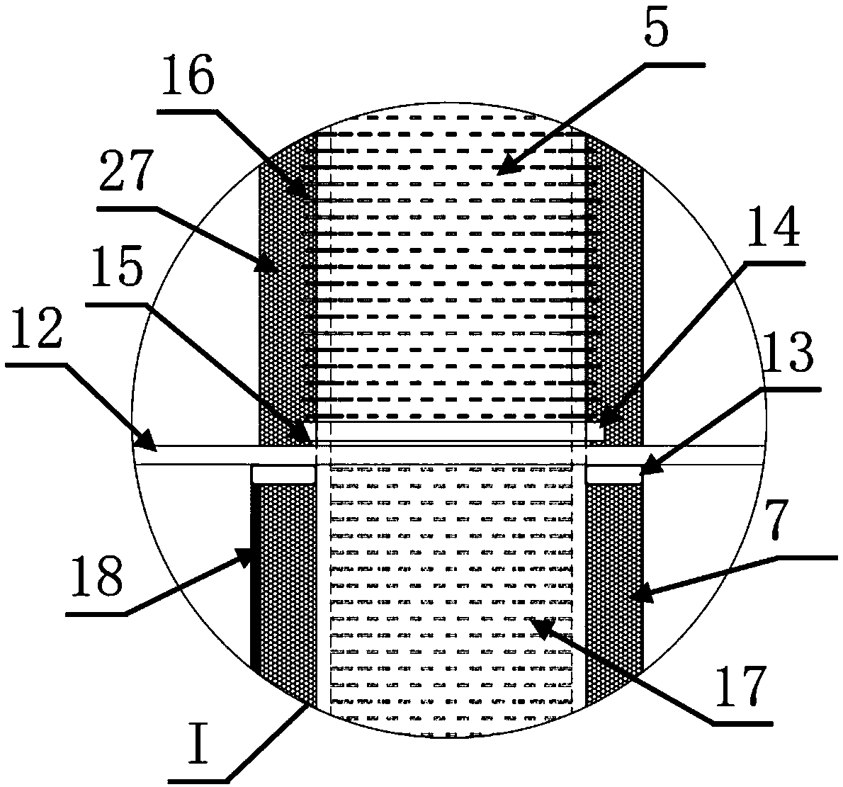
[0046] Embodiment 2: A dust-removing storage heat-exchange device used in a waste heat recovery system for classification and purification of dust-laden flue gas. Unit composition; the dust removal storage heat exchange unit includes a metal foam block 7, a filter screen 18 and several three-dimensional fin heat pipes 5; the three-dimensional fin heat pipes 5 are arranged side by side in the longitudinal direction, and each three-dimensional fin heat pipe 5 is inserted into the foam metal block 7 In the middle; the outside of the left end of the metal foam block 7 is provided with a stainless steel filter screen 18; the upper end of the three-dimensional rib heat pipe 5 passes through the partition plate 12 and enters the cooling medium channel 11b, and extends upwards as the heat pipe condensation section 20; The three-dimensional rib heat pipe 5 in the flue gas channel 11a is used as the heat pipe evaporation section 20; the inside of the three-dimensional rib heat pipe 5 is ...

Embodiment 3

[0054] Example 3, the method of using the waste heat recovery system for the classified purification of dusty flue gas to recover the waste heat of dusty flue gas is as follows: industrial dusty flue gas flows into the flue gas channel from the flue gas inlet 2, and flows through the first stage dust removal storage In the heat exchange unit, the fly ash particles with larger particle size are removed by the large-pore filter screen and the metal foam block, and the flue gas transfers heat to the metal foam block with large specific heat capacity and the three-dimensional rib heat pipe. Afterwards, the flue gas passes through the multi-stage dust removal and storage heat exchange unit successively, and the fly ash particles in the flue gas are removed by the filters 18 of each level and the metal foam block, and the waste heat of the flue gas is evaporated and absorbed by the working fluid in the evaporation section of the heat pipe, and finally The purified low-temperature flu...


PUM


Abstract

The invention discloses a dust-laden flue gas classification purification waste heat recovery system and a dedusting heat storage and exchange device. The dust-laden flue gas classification purification waste heat recovery system comprises a shell which is of an empty cuboid structure, and the middle part of the shell is provided with a separating plate; the shell is divided into an upper chamberand lower chamber by the separating plate; the waste heat recovery system is characterized in that the lower chamber is a flue gas channel, and the upper chamber is a cooling medium channel; the leftend of the flue gas channel is provided with a flue gas inlet, and the right end of the flue gas channel is provided with a flue gas outlet; the lower end of the flue gas channel is provided with a terraced cleanout door; the left end of the cooling medium channel is provided with a cooling medium outlet, and the right end of the cooling medium channel is provided with a first cooling medium inlet; the flue gas channel is internally provided with the dedusting heat storage and exchange device and an ash remover; the dedusting heat storage and exchange device is composed of a plurality of dedusting heat storage and exchange units arranged side by side transversely; each dedusting heat storage and exchange unit comprises a foam metal block, a filter screen and a plurality of three-dimensional ribbed heat pipe; and the waste heat recovery system can be widely applied to waste heat recovery of industrial flue gas.

Description

technical field [0001] The invention relates to recovery of waste heat from dusty flue gas purification, in particular to a dusty flue gas graded purification waste heat recovery system and a dust removal storage heat exchange device. Background technique [0002] At present, there is a large gap between my country's energy consumption per unit of product and developed countries, and the energy utilization level still lags behind the international advanced level. An important reason for this problem is the direct discharge of medium and low-temperature waste gas from high-energy-consuming industries such as metallurgy, chemical industry, and building materials. The direct discharge of these medium-low temperature and high dust-containing gases not only leads to serious environmental pollution, but also causes a large amount of waste heat. Waste of resources. According to statistics, flue gas waste heat accounts for 35% of my country's residual energy, which is equivalent to...

Claims


Application Information

Patent Timeline
IPC IPC(8): F28D15/02B01D46/10B01D46/24
CPCB01D46/10B01D46/2455B01D2258/0283F28D15/0233
Inventor 丁玉栋廖强张俊楠程旻付乾朱恂王宏李俊张亮
Owner CHONGQING UNIV
Why Eureka
Try Eureka