
Corrugated pipe azimuth adjustment displacement detection device and method thereof

A technology of displacement detection and orientation adjustment, which is applied in the direction of measuring devices, optical devices, instruments, etc., can solve the problems of low degree of automation, high price of laser three-dimensional scanning sensors, and high labor intensity.

Active Publication Date: 2019-03-19
CHANGZHOU INST OF TECH
View PDF23 Cites 6 Cited by
  • Summary
  • Abstract
  • Description
  • Claims
  • Application Information

AI Technical Summary

Problems solved by technology

[0003] There are not many domestic reports on the wave pitch detection of bellows expansion joints. The conventional method uses manual measurement, which has low efficiency, poor measurement accuracy, high labor intensity, and a low degree of automation.
Jiangsu Special Equipment Safety Supervision and Inspection Research Institute constructed the mechanical structure of the bellows expansion joint measuring device and adopted laser three-dimensional scanning technology to realize the point cloud acquisition of the surface waveform data of the bellows expansion joint and through the least square method and curve fitting The combined algorithm realizes noise filtering and effective signal extraction, but in the above detection method, the bellows are either stationary or rotating on the plane, and the laser three-dimensional scanning sensor installed on the industrial robot can approach or stay away from the bellows in the horizontal direction, or Detection of bellows at different heights by lifting
The laser 3D scanning sensor it uses is expensive, and requires algorithmic screening and fitting of the cloud point data, and the device can only measure the axial displacement of the bellows

Method used


Image

  • Corrugated pipe azimuth adjustment displacement detection device and method thereof

Examples


Embodiment Construction

[0022] The present invention will be described in further detail below in conjunction with the accompanying drawings.

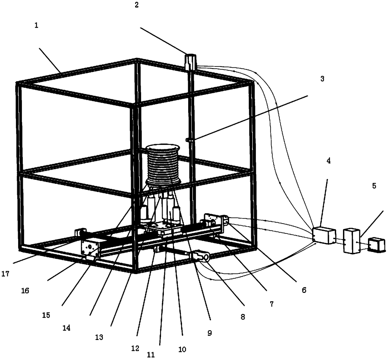
[0023] The invention provides a laser sensor displacement detection device and method for azimuth adjustment of bellows expansion joints. The structure of the device is as figure 1 shown.

[0024] Method of the present invention comprises the steps:

[0025] Step 1: Build a laser ranging sensor bellows expansion joint azimuth adjustment detection device

[0026] like figure 1 As shown, an industrial robot 2 is installed on the outside of the aluminum profile frame 1, and a laser ranging sensor 3 is installed on the industrial robot. The power and data lines of the industrial robot and the laser ranging sensor are connected to the industrial computer 4 and the computer 5.

[0027] The first stepper motor 6, the first screw mandrel 16 and the first guide rail 7 are installed on the lower side of the aluminum profile frame, and the second stepper motor 8, th...


PUM


Abstract

The invention discloses a corrugated pipe azimuth adjustment displacement detection device and a method thereof. The device comprises a frame, wherein a distance laser sensor and an industrial robot are arranged on the frame, a power supply and a USB cable of the distance laser sensor and the industrial robot are connected to an industrial personal computer, the industrial personal computer is connected with a computer, the frame is provided with a transverse displacement driving device and a longitudinal displacement driving device, wherein the longitudinal displacement driving device transversely moves under the drive of the transverse displacement driving device, a corrugated pipe is arranged on the longitudinal displacement driving device, the corrugated pipe longitudinally moves underthe drive of the longitudinal displacement driving device, the corrugated pipe is connected with the longitudinal displacement driving device through an electric extension rod, and three electric extension rods are installed in an equilateral triangle at equal intervals. According to the invention, displacement measurement can be realized from different azimuth angles by controlling the positionsof the corrugated pipe and the laser sensor, thereby the cost is low, and the detection method is more comprehensive.

Description

technical field [0001] The invention relates to a detection device and method for a bellows, in particular to a displacement detection device and method for a laser sensor for adjusting the orientation of the bellows. Background technique [0002] With the rapid development of the national economy, pipelines are widely used in the fields of heating, heat supply, oil and gas transportation, and various industrial supplies manufacturing. However, due to changes in pipeline temperature and pressure during transportation, pipelines will expand with heat and contract with cold, and move and deform. If these changes cannot be compensated, serious pipeline transportation safety accidents will occur. Therefore, as an elastic element that can absorb the expansion and contraction caused by thermal expansion and contraction, the expansion joint can improve the reliability and safety of pipeline transportation, and thus has been widely used. [0003] There are not many domestic reports...

Claims


Application Information

Patent Timeline
IPC IPC(8): G01B11/02
CPCG01B11/02
Inventor 许清泉徐雨果陈功郁佳艳陈子文郑倩张振兴胡文耀王臣杨紫茹张奎鹏陈全海
Owner CHANGZHOU INST OF TECH
Learn More