
a sonic detector

A technology of acoustic wave detector and semiconductor, which is applied in the direction of instruments, measuring ultrasonic/sonic wave/infrasonic wave, measuring device, etc. It can solve the problems of single control mode of acoustic wave detector and unfavorable detection of sound waves, etc., and achieve the effect of flexible frequency adjustment characteristics

Active Publication Date: 2021-09-28
山东鲁勘集团有限公司
View PDF6 Cites 0 Cited by
  • Summary
  • Abstract
  • Description
  • Claims
  • Application Information

AI Technical Summary

Problems solved by technology

[0007] The purpose of the present invention is to overcome the problem that the existing sound wave detector has a single control mode, which is not conducive to the detection of sound waves in a wide frequency range

Method used


Image

  • a sonic detector
  • a sonic detector
  • a sonic detector

Examples


Embodiment 1

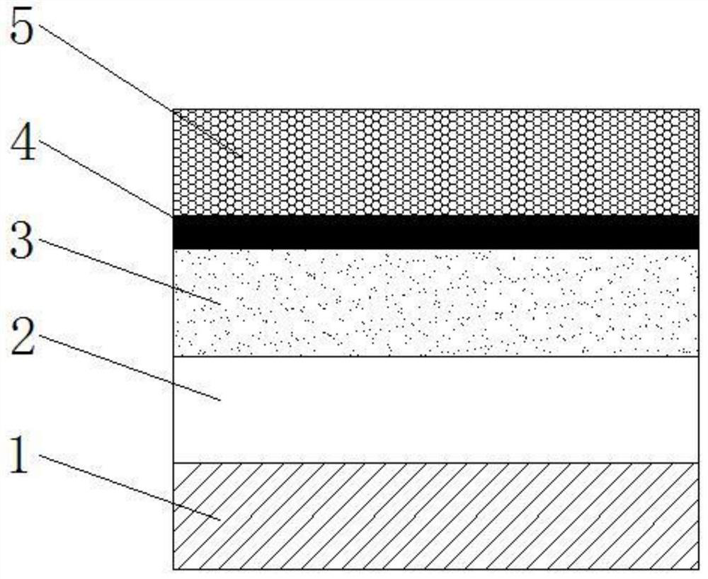
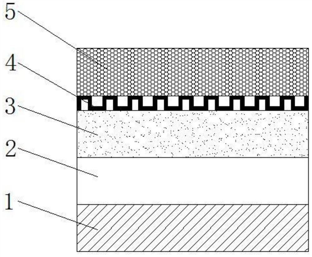
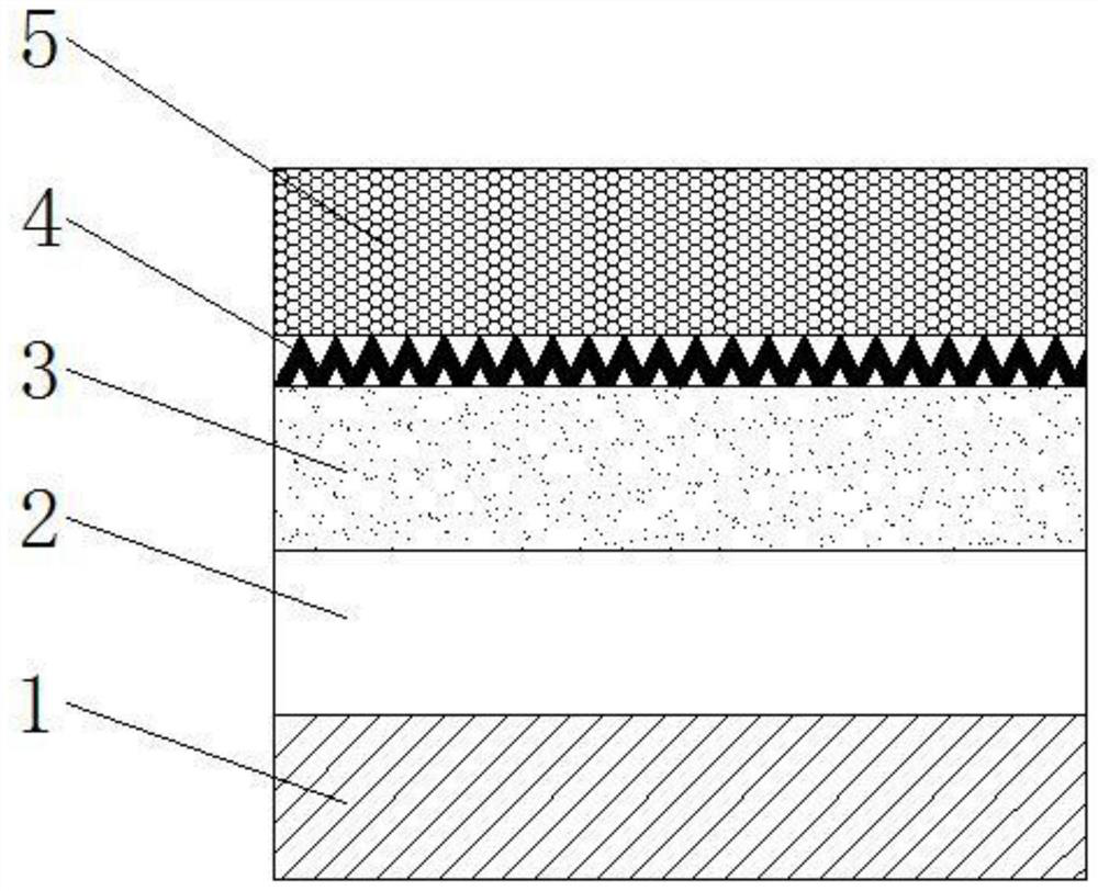
[0031] In order to overcome the problem that the existing sound wave detector has a single control mode, which is not conducive to detecting sound waves in a wide frequency range. The present invention provides a figure 1 The acoustic wave detector shown includes a substrate layer 1, which mainly plays a supporting role. The substrate layer 1 can be made of silicon dioxide, quartz, glass, etc., and a semiconductor layer 2 is arranged above the substrate layer 1. , the semiconductor layer 2 can be electrically connected to the electrodes of the external power supply, thereby forming a gate control voltage, forming a controllable electric field between the graphene layer 5 and the semiconductor layer 2, through which the dielectric of the graphene layer 5 can be regulated Constant, the top of the semiconductor layer 2 is provided with an insulating layer 3, the insulating layer 3 isolates the detection voltage loaded by the graphene layer 5 and the gate control voltage loaded by...


PUM


Abstract

The invention relates to an acoustic wave detector, comprising a substrate layer, a semiconductor layer is arranged above the substrate layer, an insulating layer is arranged above the semiconductor layer, a flexible carrier layer is arranged above the insulating layer, and the flexible A graphene layer is arranged above the carrier layer. The acoustic wave detector transmits the sound wave to the graphene layer to generate deformation, which causes the dielectric constant of the graphene layer to change. By detecting the change of the voltage loaded on the graphene layer, the Acoustic detection; at the same time, the semiconductor layer of the acoustic wave detector can be electrically connected with the regulating voltage, so as to serve as a grid to regulate the dielectric constant of the graphene layer; it can also directly enter the graphene layer through the incident light, so that the graphene layer The dielectric constant is changed to regulate the dielectric constant of the graphene layer.

Description

technical field [0001] The invention relates to the technical field of acoustic wave detection, in particular to an acoustic wave detector. Background technique [0002] Acoustic detectors are becoming very important today, either as part of speech transmission devices or as part of photoacoustic detectors in gas analyzers for analyzing gases, for example ambient air. [0003] Commonly used acoustic sensors are designed as capacitive sensors with two diaphragms which are spaced apart from each other and define a capacitor. One of the diaphragms is fixed and the other is displaceable by the sound waves to be detected. The displacement of the movable diaphragm determines the capacitance change of the capacitor, which can be detected by a suitable readout circuit and output as an electrical signal from which properties of the sound wave to be detected, such as the sound pressure, can be deduced. [0004] Although capacitive acoustic wave detectors are characterized by high se...

Claims


Application Information

Patent Timeline
Patent Type & Authority Patents(China)
IPC IPC(8): G01H11/06
CPCG01H11/06
Inventor 邓海蛟张中侠王天堃
Owner 山东鲁勘集团有限公司
Learn More