Robot for implanting radioactive particles

A technology of radioactive particles and robots, applied in the field of robots implanted with radioactive particles, can solve problems such as low puncture accuracy, poor reliability, and injury to surgeons, and achieve high puncture positioning accuracy, good safety and reliability, and high degree of automation Effect

Pending Publication Date: 2019-03-22
SHENZHEN INST OF ADVANCED TECH
View PDF11 Cites 20 Cited by
  • Summary
  • Abstract
  • Description
  • Claims
  • Application Information

AI Technical Summary

Problems solved by technology

[0003] At present, most of the medical particle implantation radiotherapy devices rely on doctors to manually operate the implantation treatment based on their experience. This method cannot continuously and automatically implant particles. The operation time is long, it is easy to make the doctor tired, and the treatment efficiency is low. Radioactive particles have certain effects on the surgeon. radiation damage
In addition, the invention of patent CN104162226B provides an automatic device for continuous and automatic implantation of radioactive particles, which provides a detachable clip to store radioactive particles, and does not require doctors to manually implant particles; but the device is installed at the end of the mechanical arm. The puncture of the outer needle is achieved through the motion control of the mechanical arm. The motion control is complex and the puncture accuracy is poor; and the adjustment of the puncture posture needs to rely on the coordinated control of the joint components of the mechanical arm, resulting in complex overall control, high cost, and large overall volume.
Patent CN205127113U discloses an electric particle implantation device for brachytherapy. The puncture move

Method used


Image

  • Robot for implanting radioactive particles
  • Robot for implanting radioactive particles
  • Robot for implanting radioactive particles

Examples


Embodiment Construction

[0038] In order to make the object, technical solution and advantages of the present invention clearer, the present invention will be further described in detail below in conjunction with the accompanying drawings and embodiments. It should be understood that the specific embodiments described here are only used to explain the present invention, not to limit the present invention.

[0039] It should be noted that the terms "setting" and "connecting" should be understood in a broad sense, for example, they can be directly set and connected, or indirectly set and connected through a central component or a central structure.

[0040] In addition, if there are "longitudinal", "transverse", "length", "width", "thickness", "upper", "lower", "front", "rear", "left", " Terms such as "right", "vertical", "horizontal", "top", "bottom", "inner", "outer", etc. indicate the orientation or positional relationship, which are based on the orientation or positional relationship shown in the dr...


PUM


Abstract

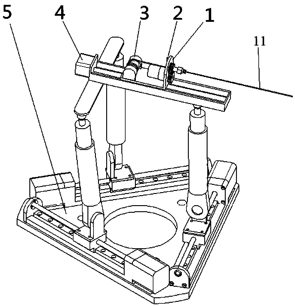
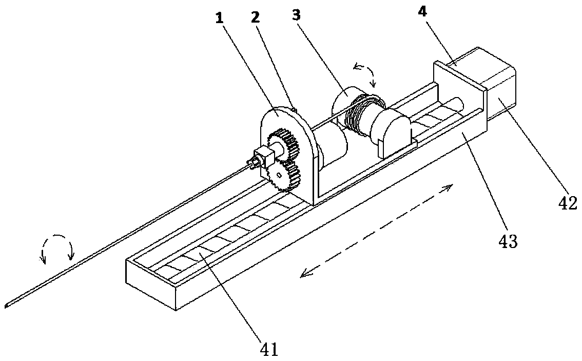
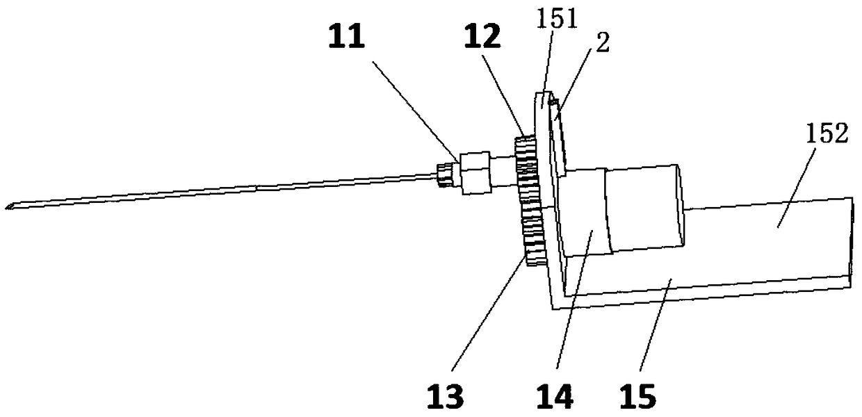
The invention is applicable to the technical field of medical instruments, and discloses a robot for implanting radioactive particles. The robot comprises an external needle puncture device, an internal needle device, a clip device and a posture control device; the external needle puncture device comprises a first supporting frame and a rotatable external needle puncture tube; the internal needledevice comprises an internal needle and an inner needle driving component, the front end of the internal needle can extend into the external needle puncture tube, and the inner needle driving component is used for driving the internal needle to slide along the external needle puncture tube; the external needle puncture device is connected to the posture control device. The robot for implanting theradioactive particles can automatically and continuously implant the radioactive particles and is high in automation degree and excellent in safety and reliability, extrusion of target tissues (target spots) by the external needle puncture tube can be effectively eliminated by rotation of the external needle puncture tube, puncture positioning precision is higher, radioactive particle implantingeffects are better, and the robot is compact in structure and excellent in application effect.

Description

technical field [0001] The invention belongs to the technical field of medical devices, in particular to a robot for implanting radioactive particles. Background technique [0002] Radioactive seed implantation therapy is a special radiation therapy method of radiation therapy. Radiation therapy is one of the three major treatment methods for tumor treatment. Most tumor treatments require radiation therapy. Particle implantation radiotherapy is a minimally invasive surgical treatment method, which has the advantages of simple operation, less trauma in the treatment process, and good treatment effect. At present, seed implantation therapy is mainly applied to malignant tumors including: breast cancer, liver cancer, brain tumor, prostate tumor, head and neck tumor and adrenal gland tumor. [0003] At present, most of the medical particle implantation radiotherapy devices rely on doctors to manually operate the implantation treatment based on their experience. This method cann...

Claims


Application Information

Patent Timeline
IPC IPC(8): A61N5/10A61B17/34A61B34/30
CPCA61N5/1007A61N5/1014A61B17/3468A61B34/30A61N2005/1012A61N2005/1009A61B2034/302
Inventor 熊璟甘志坚夏泽洋
Owner SHENZHEN INST OF ADVANCED TECH
Why Eureka
Try Eureka