
A cvi process method for preparing carbon/carbon crucible based on flow field optimization

A process method and carbon crucible technology are applied in the field of CVI process for preparing carbon/carbon crucibles based on flow field optimization, which can solve the problems of airflow blocking, crucible cracks, no longer uniform precursors, etc., to ensure uniformity, reduce cycle and cost effect

Active Publication Date: 2021-03-02
上海康碳复合材料科技有限公司 +1
View PDF7 Cites 0 Cited by
  • Summary
  • Abstract
  • Description
  • Claims
  • Application Information

AI Technical Summary

Problems solved by technology

The carbon / carbon composite material crucible has a heating and cooling process in use, and the thermal expansion coefficients of different textures are also different, resulting in internal thermal stress concentration, coupled with the thermal vibration generated during the pulling process of single crystal silicon, resulting in the inside of the crucible Crack
[0006] Patent (CN 103193498 A) through the synergistic effect of narrow slit airflow and inductive coupling, although the surface crusting phenomenon can be effectively suppressed, because there are interlaced burrs on the surface of the preform, which have a blocking effect on the airflow, it is easy to form tiny eddy currents in the space of interlaced burrs. zone, so that the residence time of the gas flowing through the slit is prolonged, and the precursor near the surface of the preform becomes inhomogeneous
In addition, the patent (CN 103193498 A) adopts lower air intake, and the macromolecular substances generated by the pyrolysis of hydrocarbon gas in the narrow space are carried by the strong gas flow to the surface of the crucible prefabricated body and enter the pores to further crack into carbon. Molecular substances can easily block the internal pores, making it difficult for subsequent gases to enter. It is difficult to continue to increase when the crucible is deposited to a certain density, and multiple machining and multiple depositions are required to achieve the desired density.

Method used


Image

  • A cvi process method for preparing carbon/carbon crucible based on flow field optimization
  • A cvi process method for preparing carbon/carbon crucible based on flow field optimization
  • A cvi process method for preparing carbon/carbon crucible based on flow field optimization

Examples


Embodiment 1

[0038] The basic steps of the first stage:

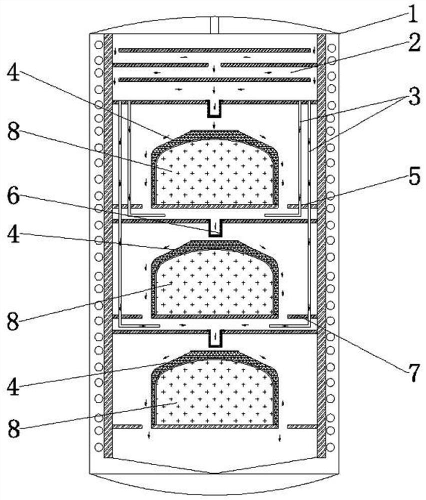
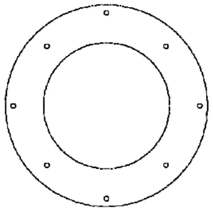
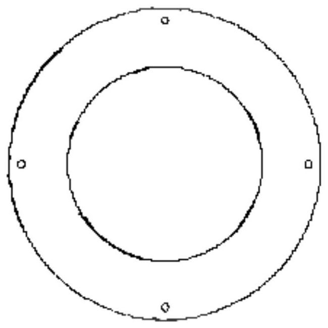
[0039] 1) Furnace loading, the carbon fiber crucible prefabricated body 4 according to the following figure 1 The shown is loaded in the high-temperature vapor deposition furnace 1, and 2 in the figure is the preheating zone, and three preforms can be placed in the constant temperature zone, and the number of preforms can be appropriately adjusted according to the size of the constant temperature zone. The support plates are separated by graphite pillars (graphite pillars are not shown in the figure). From top to bottom, the gas supply pipeline 3 appears from the second crucible preform, and the number of gas supply in each layer is 4. The top view of the graphite support plates 5 and 7 is as follows diagram 2-1 with Figure 2-2 As shown, the air supply pipeline 3 is made of quartz material. The inside of the crucible prefabricated body 4 is filled with a graphite or quartz lining 8, and the outer surface of the inner lining 8 i...

Embodiment 2

[0055] The basic steps of the first stage:

[0056] 1) Furnace loading, the carbon fiber crucible prefabricated body 4 according to the following figure 1 Filling is carried out as shown, three prefabricated bodies can be placed in the constant temperature zone, and the number of prefabricated bodies can be adjusted appropriately according to the size of the constant temperature zone. The support plates are separated by graphite pillars (graphite pillars are not shown in the figure). From top to bottom, the gas supply pipeline 3 appears from the second crucible preform, the number of gas supply in each layer is 4, and the gas supply pipeline 3 is made of quartz material. The inside of the crucible prefabricated body 4 is filled with a graphite or quartz lining 8, and the outer surface of the inner lining 8 is close to the inner surface of the crucible prefabricated body 4;

[0057] 2) Check the airtightness of the high-temperature vapor deposition furnace by vacuuming, start...

Embodiment 3

[0072] The basic steps of the first stage:

[0073] 1) Furnace loading, the carbon fiber crucible prefabricated body 4 according to the following figure 1 Filling is carried out as shown, three prefabricated bodies can be placed in the constant temperature zone, and the number of prefabricated bodies can be adjusted appropriately according to the size of the constant temperature zone. The support plates are separated by graphite pillars (graphite pillars are not shown in the figure). From top to bottom, the gas supply pipeline 3 appears from the second crucible preform, the number of gas supply in each layer is 4, and the gas supply pipeline 3 is made of quartz material. The inside of the crucible prefabricated body 4 is filled with a graphite or quartz lining 8, and the outer surface of the inner lining 8 is close to the inner surface of the crucible prefabricated body 4;

[0074] 2) Check the airtightness of the high-temperature vapor deposition furnace by vacuuming, start...


PUM


Abstract

The invention discloses a CVI process method for preparing a carbon / carbon crucible based on flow field optimization, which includes two stages. In the first stage, a crucible prefabricated body containing an inner liner is placed in a high-temperature vapor deposition furnace for deposition, and the crucible prefabricated body has sufficient After the strength, the surface of the crucible preform is machined; in the second stage, an external mold is installed on the outside of the machined crucible preform, and an internal mold is close to the inner surface of the machined crucible preform, and vapor deposition is performed for the second time, and the external mold There are oblique holes on the upper surface, so that the airflow generates spiral rotation and enters the gap between the external mold and the crucible prefabricated body. The invention can reduce the number of times of starting the furnace as far as possible, and greatly saves the cost.

Description

technical field [0001] The invention relates to a CVI process method for preparing a carbon / carbon crucible based on flow field optimization. Background technique [0002] The high demand for clean energy promotes the rapid development of the photovoltaic industry, making the demand for polysilicon and monocrystalline silicon increasingly strong. Efficient production of high-purity monocrystalline silicon has become a key link for the sustainable development of the photovoltaic industry. In the preparation of solar cells, high-purity polysilicon is used to draw monocrystalline silicon rods. The drawing process involves the use of quartz crucibles and graphite crucibles. The quartz crucible will become soft under the action of up to 1400°C-1600°C, and its supporting role It must be provided by the graphite crucible outside. There will be impact during the pulling process. At this time, the shortcomings of graphite crucible, such as low strength and poor thermal shock perform...

Claims


Application Information

Patent Timeline
Patent Type & Authority Patents(China)
IPC IPC(8): C04B35/83
CPCC04B35/83C04B2235/614
Inventor 邵忠贾林涛吴彪
Owner 上海康碳复合材料科技有限公司
Learn More