Threaded metal yielding anchor rod device

A kind of technology of letting the pressure bolt and thread type, applied in the installation of bolts, mining equipment, earth-moving drilling and other directions, can solve the limitation of the tensile strength of the elongation anchor cable, the pressure can not be continuously carried out, and the deformation of the rock mass is lost. Can wait for the problem to achieve the effect of good integration, good pressure effect, and full contact.

Inactive Publication Date: 2019-03-22
SHAANXI COAL & CHEM TECH INST
View PDF6 Cites 3 Cited by
  • Summary
  • Abstract
  • Description
  • Claims
  • Application Information

AI Technical Summary

Problems solved by technology

[0002] In the support of geotechnical engineering, tunnel engineering, and slope engineering, the common support equipment is anchor rod and anchor cable. Traditional support equipment often adopts rigid structures due to material and structural limitations. The elongation of the anchor rod The pull-out force of the anchor cable and the anchor cable are limited. For geological conditions where rock mass cracks are relatively developed and deformation and damage are relatively large, support failures often occur, resulting in dangerous situations such as surrounding rock instability. energy-consuming bolts / cables to solve engineering support problems
[0003] The existing large-deformation bolts / cables are mainly divided into two types in terms of function: one is to use special flexible materials as the rod body and anchor cable structure, and to use the special properties of flexible materials to allow larger Deformation load, the ductility of this type of material is generally high, and the cost is relatively high; the second type is to install a special compressive structure in the anchor rod and anchor cable. Use friction or compression to lose the deformation energy of the rock mass, so that the bolt / cable can produce constant resistance or variable resistance and other decompression effects. This is usually done by setting a pressure relief ring, but the existing pressure relief ring They are all discontinuous, resulting in the inability to carry out the pressure yielding effect continuously

Method used


Image

  • Threaded metal yielding anchor rod device
  • Threaded metal yielding anchor rod device
  • Threaded metal yielding anchor rod device

Examples


Embodiment Construction

[0037] The following further describes the present invention in detail with reference to specific embodiments, which is an explanation rather than a limitation to the present invention.

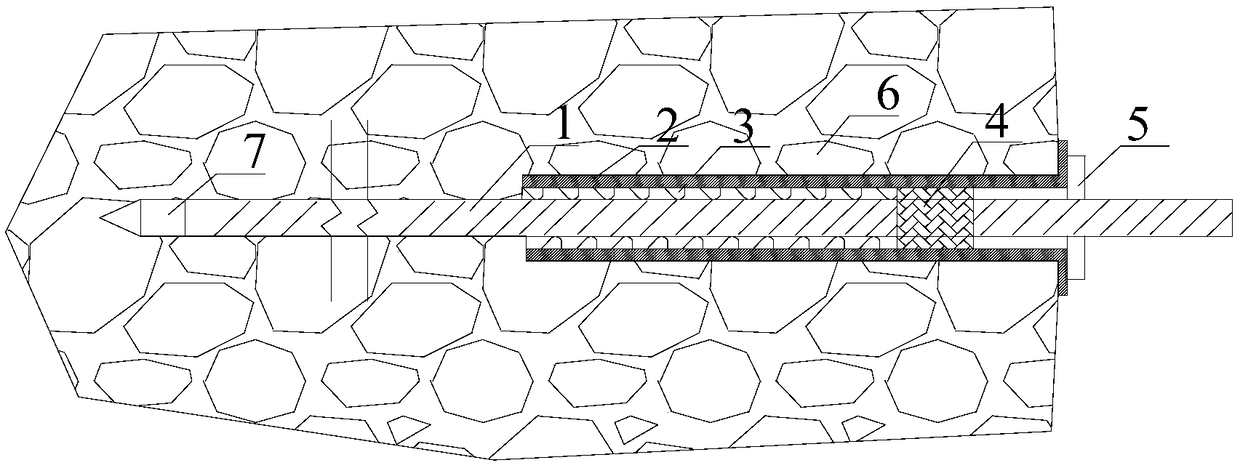
[0038] The threaded metal pressure letting bolt device of the present invention includes a fixed anchor head 7, an anchor rod body 1, a metal head 4, a metal protective sleeve 2 and a threaded pressure letting ring 3.

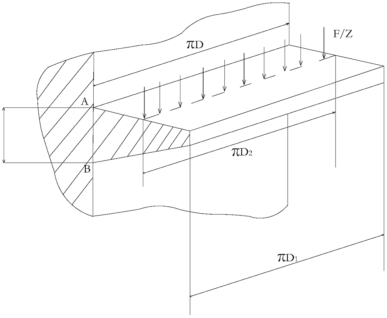
[0039] The thread allows the pressure ring 3 to be arranged in the metal protective sleeve 2 in the form of an internal thread, and the thread allows the pressure ring 3 and the metal protective sleeve 2 to be integrally formed. In this embodiment, a metal rod is used to directly turn a metal protective sleeve 2 with a threaded pressure ring 3 through turning. In addition, in this embodiment, the thread makes one side tooth surface of the pressure ring 3 a curved surface, and the other side tooth surface is a vertical surface perpendicular to the axial direction of the metal protec...


PUM


Abstract

The invention provides a threaded metal yielding anchor rod device including a fixed anchor head, an anchor rod body, a metal head, a metal protection sleeve and a thread yielding ring. The thread yielding ring is disposed in the metal protection sleeve in the form of an internal thread, and the diameter of the metal head is greater than the minor diameter of the thread yielding ring and smaller than the internal diameter of the metal protection sleeve. During the use, the fixed anchor head is mounted in a drilled hole of a surrounding rock, and the metal protection sleeve is mounted in a drilled hole port of the surrounding rock; one end of the anchor rod body passes through the thread yielding ring and is connected with the fixed anchor head, the other end is connected with the metal head, and the metal head is placed in the metal protection sleeve. The thread yielding ring is disposed in the metal protection sleeve in the form of the internal thread, since the thread is continuous and uninterrupted and there is no gap between two yielding rings, when the metal head causes axial deformation of the thread yielding ring, an acting force is continuous, a stable and continuous yielding effect is generated, and the yielding effect is improved.

Description

Technical field [0001] The invention belongs to the field of supporting equipment for underground engineering in coal mines, and specifically relates to a threaded metal pressure letting bolt device. Background technique [0002] The common supporting equipment in the support of geotechnical engineering, tunnel engineering, and slope engineering is anchor rod and anchor cable. Traditional supporting equipment often adopts rigid structure due to the limitation of material and structure, and the elongation rate of anchor rod There are restrictions on the pull-out resistance of the anchor cable and the anchor cable. For geological conditions with relatively developed rock mass fractures and large deformation damage, support failures often occur, resulting in dangerous conditions such as instability of the surrounding rock, and it is urgent to adopt a method that can tolerate large deformations Energy-consuming bolts / cables to solve engineering support problems. [0003] The existing ...

Claims


Application Information

Patent Timeline
Patent Type & Authority Applications(China)
IPC IPC(8): E21D21/00
CPCE21D21/0006E21D21/0033E21D21/0093
Inventor 种阳黄克军邓增社王苏建李涛丁国峰王荣泉金声尧赵萌烨胡魏魏
Owner SHAANXI COAL & CHEM TECH INST
Why Eureka
Try Eureka