Associated gas treatment plant section plug-flow collecting system and method

A slug flow and associated gas technology, applied in pipeline systems, gas/liquid distribution and storage, mechanical equipment, etc., can solve the problems of large overall volume of capture equipment, difficult equipment installation/transportation, and poor adaptability in the later stage. Small footprint, quick installation and stable flow

Pending Publication Date: 2019-03-22
CHINA PETROLEUM ENG & CONSTR +1
View PDF0 Cites 1 Cited by
  • Summary
  • Abstract
  • Description
  • Claims
  • Application Information

AI Technical Summary

Problems solved by technology

As mentioned above, due to the low operating pressure of the associated gas pipeline, the pipe diameter is often large, so the associated gas pipeline accumulates more liquid in winter (due to the low ground temperature in winter, the associated gas in the pipeline is more likely to precipitate condensate), and the flow rate is under pressure. The impact of fluctuations varies greatly, and the single slug flow load is relatively large; in addition, in order to meet the requirements of gas

Method used


Image

  • Associated gas treatment plant section plug-flow collecting system and method

Examples


Embodiment Construction

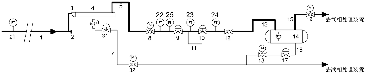
[0026] A slug capture system for an associated gas treatment plant, including a pressure-flow detection system, a gas-liquid-solid separation pipeline system, a double-regulating valve pressure compensation system, a gas-liquid separator, and the like.

[0027] A slug capture system for an associated gas treatment plant, such as figure 1 As shown, it mainly includes: inlet pipe section 1, turning tee 2, expanded diameter eccentric large and small joints 3, expanded diameter horizontal straight pipe 4, gas phase riser 5, liquid level control pipe 6, liquid phase pipe 7, liquid level adjustment Valve 31, electric ball valve 32, electric ball valve 8, 1# regulating valve 9, 2# regulating valve 10, release pipeline 11, manual ball valve 12, separator inlet pipe 13, gas-liquid separator 14, gas phase outlet pipe 15, Liquid phase outlet pipeline 16, liquid phase regulating valve 17, liquid phase outlet ball valve 18, gas phase outlet ball valve 19, upstream pressure transmitter 21, ...


PUM

PropertyMeasurementUnit
Lengthaaaaaaaaaa
Particle sizeaaaaaaaaaa

Abstract

The invention discloses an associated gas treatment plant section plug-flow collecting system and method. The system comprises a gas-liquid-solid separating pipeline system, a double-regulating-valvepressure compensating system, a gas-liquid separating system and a pressure-flow detecting system. The invention discloses a coping strategy and a solution for a large-range plug-flow problem, causedby pressure fluctuations under a low-pressure operation condition, of an associated pipeline. Upstream and downstream pressure jump monitoring and regulating valve control are performed through the double-regulating-valve system and the pressure monitoring system, so that restrain on large-scale section plug-flow is realized; and a diameter-expanding pipeline and a gas-liquid separator are reasonably arranged to perform small-scale section plug-flow collection, so that a large-scale section plug-flow collecting device is prevented from being directly arranged, and stable effect is also achieved for production.

Description

technical field [0001] The invention relates to a slug flow capture system and method of an associated gas treatment plant. Background technique [0002] With the continuous development of oilfield development technology, the recovery and utilization of associated gas has been paid more and more attention, and the concept of direct incineration in the past has gradually changed. Associated gas is a representative product of condensate oil fields and condensate gas fields, and its methane content is lower than that of conventional natural gas, C 3 ~C 5 High component content. Unstable associated gas is usually obtained from condensate oil by vacuum separation, and processed and recovered by a specialized associated gas treatment plant. During pipeline transportation, associated gas is susceptible to liquid phase condensation due to the influence of the environment of buried pipelines, and liquid accumulation is formed in the pipeline, which is more obvious in winter; at th...

Claims


Application Information

Patent Timeline
IPC IPC(8): F17D5/00F17D1/00F17D3/01F17D3/14
CPCF17D1/00F17D3/01F17D3/14F17D5/00
Inventor 陈俊文刘慧敏祝疆代卿余洋郭艳林杨帆汤晓勇缪晖边云燕王磊昝林峰袁霄
Owner CHINA PETROLEUM ENG & CONSTR
Why Eureka
Try Eureka