
A Method of Dynamically Controlling Separator Pressure to Suppress Severe Slug Flow

A dynamic control and separator technology, applied in gas/liquid distribution and storage, pipeline systems, mechanical equipment, etc., can solve problems such as oil and gas production reduction, dead well accidents, etc., to increase oil and gas production, eliminate harmful flow patterns, and stabilize Effect of standpipe differential pressure

Active Publication Date: 2017-10-20
XI AN JIAOTONG UNIV
View PDF4 Cites 0 Cited by
  • Summary
  • Abstract
  • Description
  • Claims
  • Application Information

AI Technical Summary

Problems solved by technology

Among them, the method of suppressing severe slug flow by separator back pressure attracted the attention of scholars such as Schmidt (1985) and Taitel (1986) as early as the 1980s. The area where the flow occurs is reduced on the flow diagram, which can effectively suppress the occurrence of severe slug flow without installing additional equipment and modifying pipelines. It is the most economical and practical, but a large increase in the back pressure of the separator will cause a decrease in oil and gas production , may lead to dead well accidents in severe cases

Method used


Image

  • A Method of Dynamically Controlling Separator Pressure to Suppress Severe Slug Flow
  • A Method of Dynamically Controlling Separator Pressure to Suppress Severe Slug Flow
  • A Method of Dynamically Controlling Separator Pressure to Suppress Severe Slug Flow

Examples


Embodiment Construction

[0037] A method for dynamically controlling separator pressure to suppress severe slug flow according to the present invention will be described in detail below with reference to the accompanying drawings.

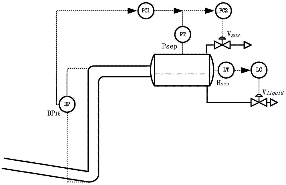
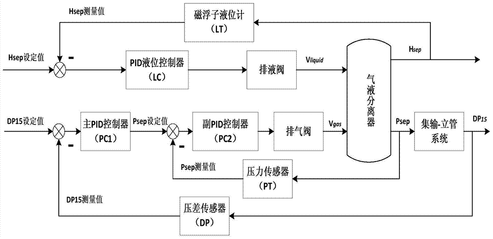
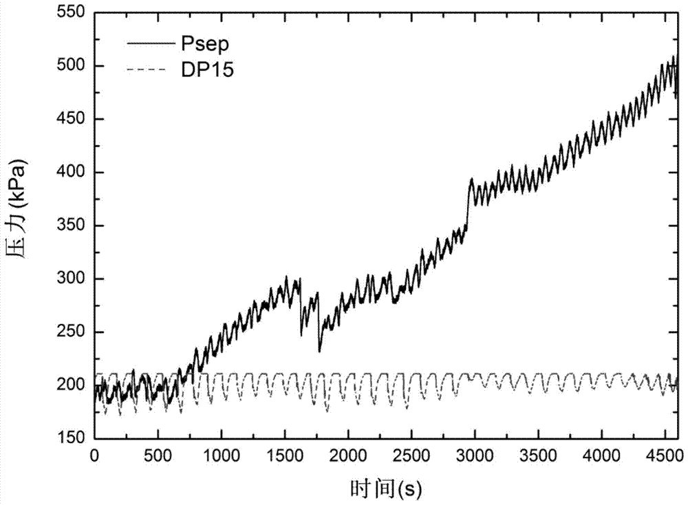
[0038] see figure 1 The structure diagram of the gathering-riser piping system shown and figure 2 The control flow chart is shown. For single-loop PID liquid level control, the controlled variable is the gas-liquid separator liquid level H sep , the control variable is the opening of the drain valve at the bottom of the gas-liquid separator V liquid , the actual liquid level of the separator measured by the magnetic float level gauge LT and H sep The set value is compared, and the difference obtained is PID logic operation through the PID liquid level controller LC, and the corresponding discharge valve opening is calculated to control the speed at which the liquid in the gas-liquid separator flows out through the discharge valve to stabilize the liquid level. ; For c...


PUM


Abstract

The invention discloses a method for dynamically controlling the pressure of a separator to suppress severe slug flow, which is applied to a gathering-riser pipeline system used in offshore oil and gas production. The gathering-riser pipeline system includes a riser and a The gas-liquid separator arranged on the top of the standpipe; the top of the gas-liquid separator on the top of the standpipe is provided with an exhaust valve, and the bottom is provided with a liquid discharge valve; the method of dynamically controlling the pressure of the separator to suppress severe slug flow includes: using gas-liquid The opening of the drain valve of the separator is the manipulated variable, and the liquid level of the gas-liquid separator is kept stable through the independent single-loop PID operation; the opening of the exhaust valve of the gas-liquid separator is used as the manipulated variable, and through the cascade PID operation, The main circuit stabilizes the pressure difference of the riser, the secondary circuit stabilizes the pressure of the gas-liquid separator, and the output of the main circuit is used as the set value of the secondary circuit; the liquid level and pressure control circuits run in parallel. The invention can keep the system stable while suppressing the severe slug flow, can greatly reduce the pressure of the separator, and increase the oil and gas production.

Description

【Technical field】 [0001] The invention belongs to the technical field of multiphase flow in petroleum engineering, and in particular relates to a control method for suppressing severe slug flow pattern of a gathering-standpipe structure in the process of offshore oil and gas production and transportation. 【Background technique】 [0002] In order to save investment and operating costs of subsea or platform projects in oil and gas fields, make full use of associated natural gas resources and reduce environmental pollution, oil and gas mixed pipelines are usually used in offshore oil and natural gas industries. However, due to the laying of submarine pipelines along complex undulating terrain and the existence of riser structures required to transport crude oil from submarine gathering and transportation pipelines to offshore platforms, multiphase mixed transportation technology brings obvious economic benefits, but also brings urgent needs. The technical problems solved, the m...

Claims


Application Information

Patent Timeline
Patent Type & Authority Patents(China)
IPC IPC(8): F17D1/00F17D3/01F17D5/00
Inventor 郭烈锦周宏亮谢晨李文升
Owner XI AN JIAOTONG UNIV
Learn More