Improved H finned tube used for waste heat recycling

A technology of waste heat recovery and finned tubes, applied in heat exchange and heating equipment, improving the field of H-shaped finned tubes, achieving the effects of reduced flow pressure loss and improved convective heat transfer coefficient

Pending Publication Date: 2019-03-22
DATANG BEIJING ENERGY MANAGEMENT +2
View PDF0 Cites 3 Cited by
  • Summary
  • Abstract
  • Description
  • Claims
  • Application Information

AI Technical Summary

Problems solved by technology

And effectively cont

Method used


Image

  • Improved H finned tube used for waste heat recycling
  • Improved H finned tube used for waste heat recycling
  • Improved H finned tube used for waste heat recycling

Examples


Embodiment Construction

[0014] The present invention will be described in more detail below in conjunction with the accompanying drawings and specific embodiments. The following examples are helpful for those skilled in the art to better understand the present invention, but do not limit the present invention in any form. And it should be pointed out that for those skilled in the art of research, improvements can be made on the basis of the concept of the present invention, which all belong to the protection scope of the present invention.

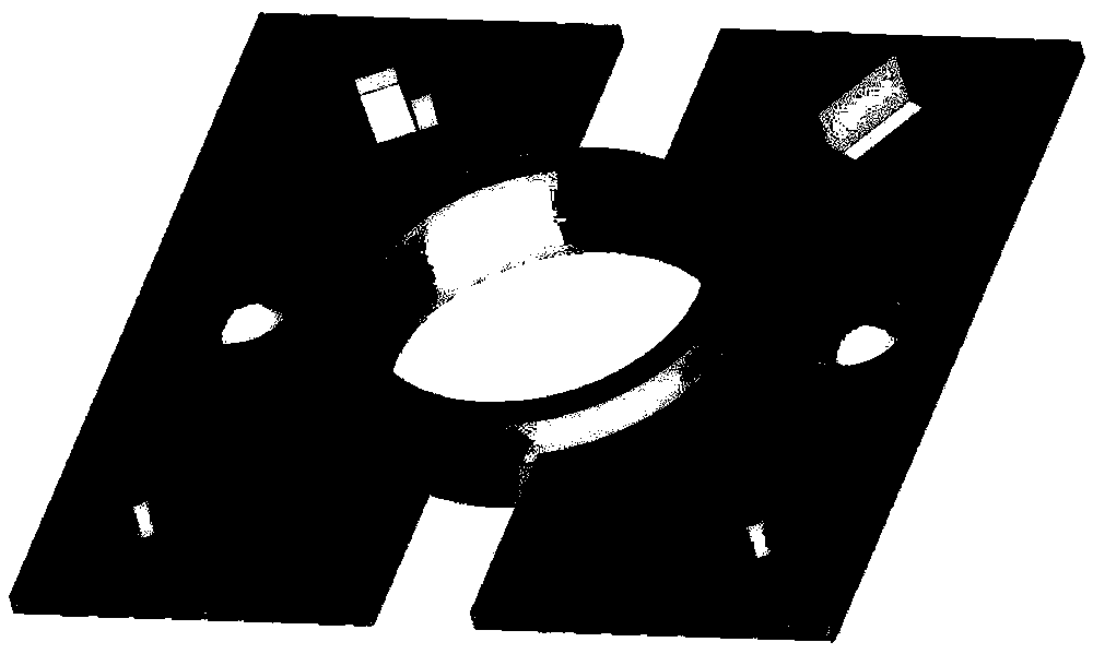
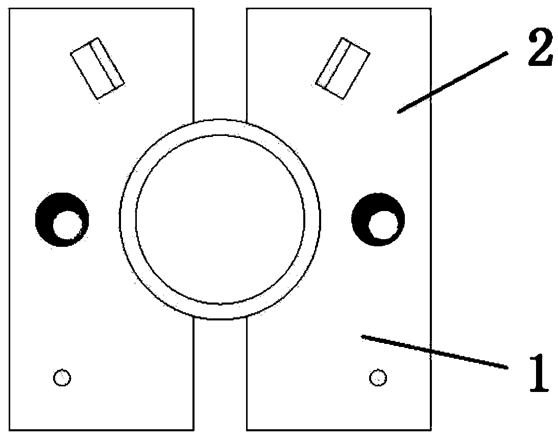
[0015] Figure 1-3 It is a structural schematic diagram of the present invention, including a circular base tube and a pair of fins.

[0016] As shown in the figure, a structurally improved H-shaped finned tube includes a base tube and a fin group. There is a flowing heat exchange working medium inside the base tube, which is generally liquid, and its heat conduction capacity is greater than that of the fluid outside the fins. The fin group includes a group of...


PUM


Abstract

The invention discloses an improved H finned tube used for waste heat recycling. The finned tube comprises a base tube and fin sets; the base tube has a certain length, multiple parallel fin sets arearranged in the axial direction of the base tube and are connected to the outer wall of the base tube, the windward sides of the fin surfaces are provided with flow disturbance rods, spherical protrusion structures are arranged at the positions, on the side of the base tube, of the center positions of the fin surfaces, and a small wing vortex generator is arranged on the leeward sides of the fin surfaces. When smoke flows past, the direction is not changed, the fins with spherical protrusions and the flow disturbance rods can change the airflow motion states, disturbance is intensified, the hysteresis heat layer thickness can be reduced, and the aim of reinforcing heat transfer is achieved to a certain degree.

Description

technical field [0001] The invention relates to an H-shaped finned tube, in particular to an improved H-shaped finned tube for waste heat recovery, which is suitable for various types of heat exchange and heating equipment in industries such as petroleum, chemical industry, metallurgy, electric power, and energy. Background technique [0002] With the continuous development of society, the demand for energy is gradually expanding. For the sustainable development of human beings, the efficient and sustainable use of energy must be paid attention to. my country's thermal power accounts for a relatively large proportion in the power industry, and the installed capacity of coal power accounts for 58.8%. To meet the requirements of sustainable development of human society, meet the national energy development plan, and actively respond to the call for energy conservation and emission reduction, it is very urgent to improve the energy utilization efficiency of thermal power units....

Claims


Application Information

Patent Timeline
IPC IPC(8): F28F3/02
CPCF28F3/02
Inventor 张国柱邱寅晨李国强张钧泰刘明
Owner DATANG BEIJING ENERGY MANAGEMENT
Why Eureka
Try Eureka