
Airflow-thermo-mechanical coupling excitation test device

A heat-mechanical coupling and test device technology, which is applied in measuring devices, machine/structural component testing, vibration testing, etc., can solve the problems of difficulty in building a seal on the end face of the rotating turntable, insufficient excitation force, airflow loss, etc., to avoid air intake The effects of deficiencies, improved efficiency, and smooth gas flow

Active Publication Date: 2019-03-22
DALIAN JIAOTONG UNIVERSITY
View PDF9 Cites 4 Cited by
  • Summary
  • Abstract
  • Description
  • Claims
  • Application Information

AI Technical Summary

Problems solved by technology

However, this kind of test equipment cannot realize the high temperature of the airflow and the temperature simulation of the tested piece because there is no airflow excitation and the temperature heating device of the tested piece; on the other hand, there is no airflow storage device at the front end of the compressed airflow supply, resulting in insufficient airflow through the air pipe. On the one hand, due to the limitation of the through holes on the turntable, most of the airflow is blocked by other areas of the turntable, and it is difficult to build a seal on the end face of the rotating turntable, which leads to the loss of most of the airflow, less airflow through the round holes of the turntable, insufficient excitation force, and low efficiency. Airflow-thermomechanical coupling excitation of components cannot be effectively realized

Method used

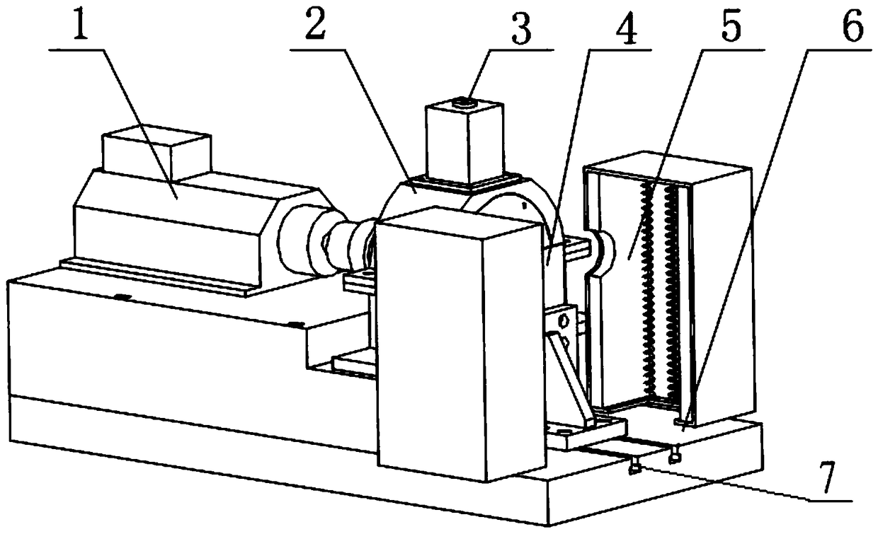
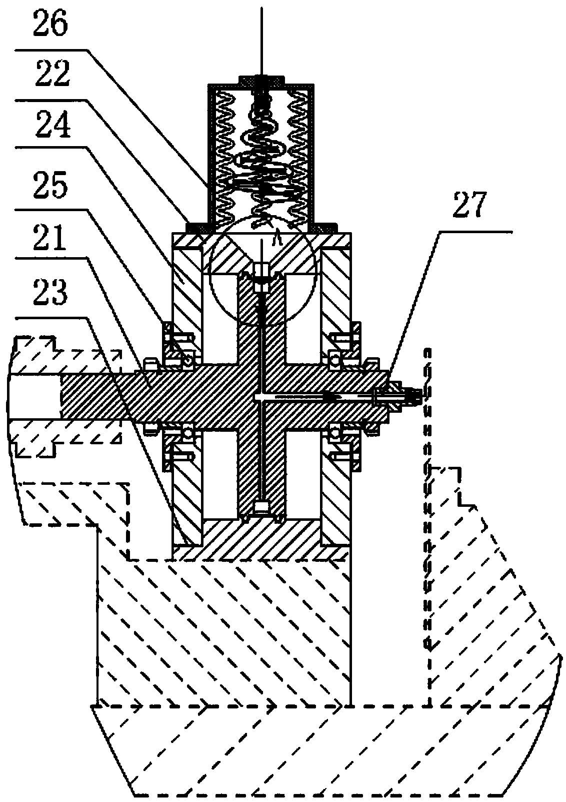
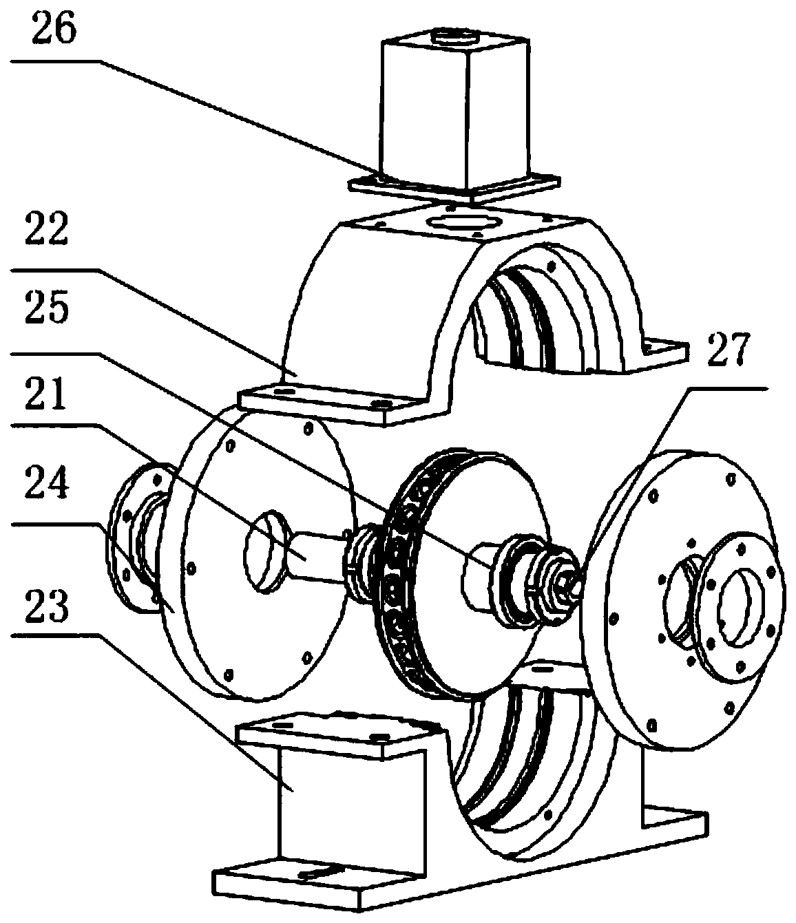

Image

  • Airflow-thermo-mechanical coupling excitation test device
  • Airflow-thermo-mechanical coupling excitation test device
  • Airflow-thermo-mechanical coupling excitation test device

Examples


Embodiment Construction

[0030] The present invention will be further described below in conjunction with the accompanying drawings and embodiments, but the patent is not limited to the structures in the illustrations, and is within the scope of protection of the patent.

[0031] Such as figure 1As shown, the airflow-heat-mechanical coupling excitation test device of the present invention consists of a drive system 1, a rotating alternating airflow generating device 2, an airflow heating device 3, a test piece and its fixture system 4, a test piece heating device 5 and a base 6 The driving system 1 is composed of a driving motor and a coupling, and the two are fixedly connected, wherein the driving motor is a variable frequency motor or a servo motor, and the rotating alternating air flow generator 2 is connected to the driving system 1, and rotates at a high speed within a certain speed range. High-frequency alternating airflow is generated; the airflow heating device 3 is used for heating the airflo...


PUM


Abstract

The invention discloses an airflow-thermo-mechanical coupling excitation test device. The device comprises a driving system, a rotary alternating airflow generating device, an air source system, an airflow heating device and a tested piece heating device, and the airflow heating device is utilized for simulating high-temperature airflow excitation; the tested piece heating device is utilized for simulating a high-temperature environment of a tested piece; an air storage box arranged on the front portion of the airflow-thermo-mechanical coupling excitation test device is adopted for storing compressed air, and air inflow amount is increased to avoid the defect of insufficient air inflowing amount; the mode of arrangement on the circumferential surface of a turntable is adopted, grate toothsealing is combined to prevent air leakage, and the efficiency of using the compressed air is improved; structures of a main shaft, a main air inlet hole of the box body, an auxiliary air inlet hole of the box body, an oval kidney-shaped hole of the main shaft, a taper hole of the box body and the like are adopted, air flowing is smooth, it is ensured that air has enough energy, and efficient high-intensity high-temperature airflow alternating excitation and simulation of the temperature environment of the tested piece are achieved.

Description

technical field [0001] The invention relates to the field of mechanical vibration test equipment. Background technique [0002] Gas turbine engine internal blades and other components are used to compress airflow or generate thrust. For example, the fan compressor blades of aeroengines are used to compress air so that compressed air enters the combustion chamber, while the turbine blades are the high-temperature gas after combustion that acts on the blades. Therefore, the blades are outside a complex airflow excitation and temperature environment, such as the low-temperature airflow and low-temperature environment on the fan blades, and the low-temperature airflow and progressively changing temperature environment on the compressor blades (about the blades close to the combustion chamber, The higher the ambient temperature), the turbine blades are in high-temperature airflow and high-temperature environment. The difference between these complex airflow excitation and tempera...

Claims


Application Information

Patent Timeline
Patent Type & Authority Applications(China)
IPC IPC(8): G01M7/02
CPCG01M7/022
Inventor 王美令温保岗
Owner DALIAN JIAOTONG UNIVERSITY
Learn More