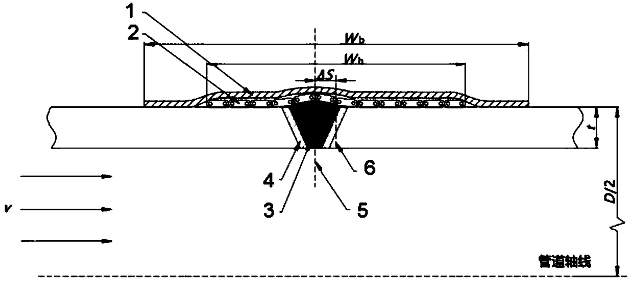
post-welding heat treatment method of Cr-Mo steel pipe with strong gas flow in the pipe
A post-weld heat treatment and steel pipe technology, applied in heat treatment furnaces, heat treatment equipment, electrical and digital data processing, etc., can solve problems such as reducing joint performance, achieve the effect of simple algorithm, ensure the quality of post-weld heat treatment, and ensure long-term safe use
Active Publication Date: 2019-03-22
ANHUI UNIVERSITY OF TECHNOLOGY
View PDF2 Cites 0 Cited by
- Summary
- Abstract
- Description
- Claims
- Application Information
AI Technical Summary
Problems solved by technology
If the maximum temperature of heat treatment deviates from the center of the heater, the maximum heating temperature of heat treatment may exceed the upper limit of the allowable heat treatment temperature, so that austenite transformation occurs in these parts during heat treatment, and hard and brittle quenched martensite is formed after cooling, which seriously reduces the performance of joints
At present, there is no relevant report on the post-weld heat treatment method of Cr-Mo steel pipe under the condition of strong air flow in the pipe
Method used
View moreImage
Smart ImageViewing Examples
Examples
Embodiment
[0055] Using a post-weld heat treatment method for a Cr-Mo steel pipe under the condition of strong air flow in the pipe according to the present invention, perform post-weld heat treatment on a Cr-Mo steel pipe, measure its temperature distribution and compare with the allowable heat treatment temperature window in the steel Range comparison to verify the accuracy of this method:
Login to View More PUM
 Abstract
The invention provides a Cr-A Mo steel pipeline post-weld heat treatment method belong to that technical field of post-weld heat treatment, and comprises a post-weld heat treatment parameter determination module, a maximum heat treatment temperature deviation distance Delta S calculation module from the heat center, and a post-weld heat treatment implementation module; It can be used to guide theflow of Cr. In long pipe under the condition of high ambient wind speed or large pressure difference between two ends of pipe. Mo steel pipe post-weld heat treatment, to ensure that the whole weld andenough base metal are in the allowable heat treatment temperature window range, so as to ensure the quality of post-weld heat treatment and ensure Cr-Mo steel pipe components are used safely for a long time.
Description
technical field [0001] The invention belongs to the technical field of post-weld heat treatment, and provides a method for post-weld heat treatment of Cr-Mo steel pipes under the condition of strong air flow in the pipe, which can be used to guide the environment caused by high wind speed or large pressure difference at both ends of long pipes. The post-weld heat treatment of Cr-Mo steel pipes under the condition of strong air flow in the pipe ensures the quality of post-weld heat treatment. Background technique [0002] Cr-Mo steel is currently the most widely used type of heat-strength steel, and is widely used in chemical industry, electric power and other equipment that need to serve in harsh environments such as high temperature, high pressure and high corrosion. Cr-Mo steel needs post-weld heat treatment after welding to improve joint performance and relax welding residual stress. During the on-site post-weld heat treatment, but limited by the construction conditions,...
Claims
Login to View More Application Information
Patent Timeline
 IPC IPC(8): G06F17/50G06N3/12C21D9/50
CPCG06N3/126C21D9/50G06F2119/08G06F30/20
Inventor 胡磊陈东旭尹孝辉马群双
Owner ANHUI UNIVERSITY OF TECHNOLOGY
Features
- R&D
- Intellectual Property
- Life Sciences
- Materials
- Tech Scout
- Unparalleled Data Quality
- Higher Quality Content
- 60% Fewer Hallucinations
Learn More Browse by: Latest US Patents, China's latest patents, Technical Efficacy Thesaurus, Application Domain, Technology Topic, Popular Technical Reports.
© 2025 PatSnap. All rights reserved.Legal|Privacy policy|Modern Slavery Act Transparency Statement|Sitemap|About US| Contact US: help@patsnap.com

