Novel nebulizer with reflux structure

A nebulizer and a new type of technology, applied in the field of nebulizers, can solve the problems of increased discomfort, aspiration, and tilt of the nebulizer for patients, so as to reduce the loss of the original drug, make the nebulizer treatment comfortable, and accurately dose the drug. Effect

Inactive Publication Date: 2019-03-26
黄梅
View PDF0 Cites 6 Cited by
  • Summary
  • Abstract
  • Description
  • Claims
  • Application Information

AI Technical Summary

Problems solved by technology

[0002] As we all know, medical nebulizers are mainly used to treat various upper and lower respiratory diseases, such as throat tumors, pharyngitis, bronchitis, asthma, cough, fever, pneumoconiosis and other diseases that occur in the trachea, bronchi, alveoli and chest cavity. The important link in the tool is the atomization of the original medicine. The amount of atomization and the size of the particles after atomization of the original medicine directly affect the therapeutic effect. The existing traditional nebulizer atomizes the medicine liquid during the atomization process. It is difficult to control the speed and particle size of the atomized original drug, which causes inconvenience in use; and the nebulizer is often used to treat children's respiratory diseases. Compared with adults, children have hyperactive habits, so children use nebulizers When the angle of inclination is large, the nebulizer may be tilted, so that the end of the suction tube immersed in the liquid is exposed to the outside of the liquid, and when the angle of inclination is large, the liquid medicine in the bottle will flow back out and flow directly to the patient's body through the pipeline. In the mouth, this will not only cause the risk of aspiration, but also increase the discomfort to the patient, so we propose a new nebulizer with a backflow structure

Method used


Image

  • Novel nebulizer with reflux structure
  • Novel nebulizer with reflux structure
  • Novel nebulizer with reflux structure

Examples


Embodiment 1

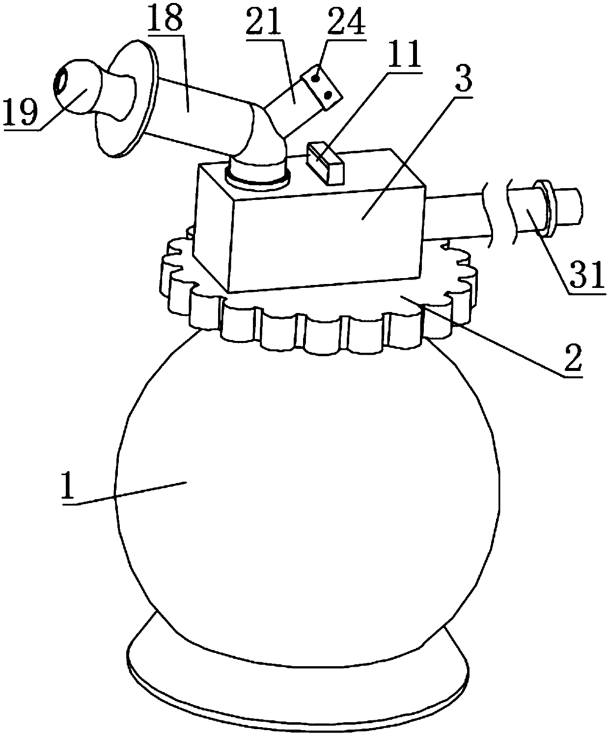
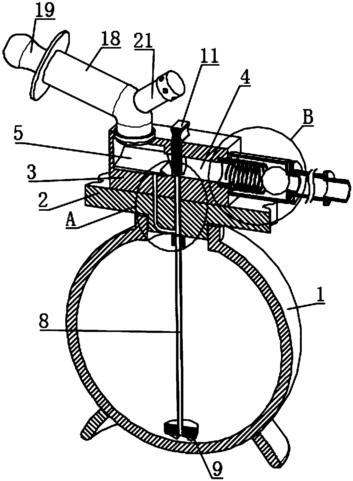
[0032] Embodiment 1, the present invention provides a technical solution: a new type atomizer with a reflux structure, including a bottle body 1 for containing liquid medicine, the inside of the bottle body 1 is spherical, and the outside shape is It can also be made into a cylindrical shape (not shown in the figure) for the convenience of holding. , both the liquid medicine and the pipette 8 will move to the lowest point after the inclination of the bottle body 1, so the bottom end of the pipette 8 is always inside the liquid medicine due to the gravity ball 9, and the atomization treatment will not be interrupted, thus To make the atomization treatment more effective, the upper side of the bottle body 1 is meshed with a sealing cover 2, and the upper side of the sealing cover 2 is fixedly connected with a fixed block 3, and the inside of the fixed block 3 is provided with an airflow channel 4 and The atomization chamber 5 and the airflow channel 4 are the channels for gas fl...

Embodiment 2

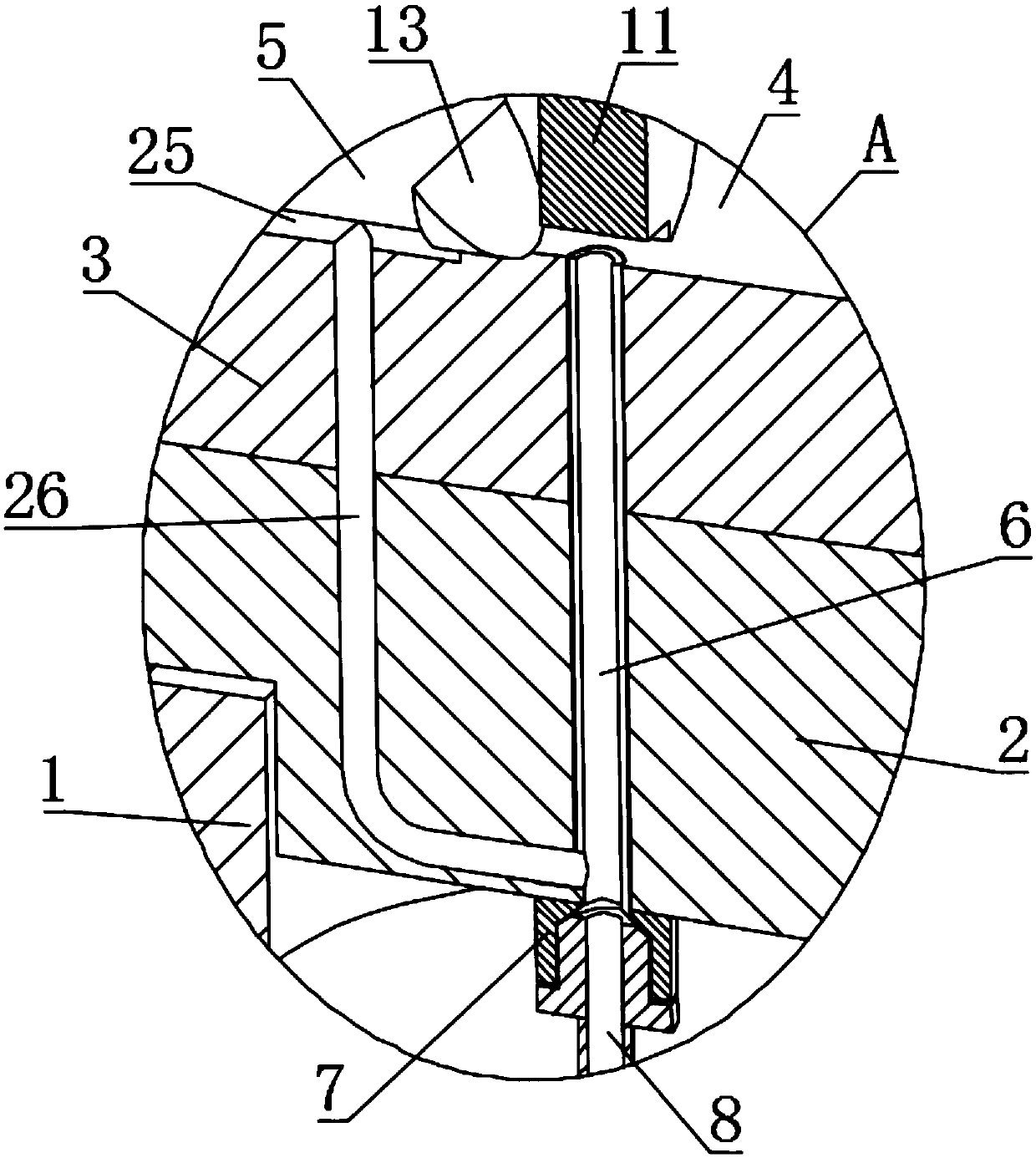
[0038] Example 2, in actual use, the atomized liquid droplets often condense on the side wall of the nebulizer. Sometimes children’s naughty causes the nebulizer to tilt, which will make the liquid pour into the mouth, causing discomfort and affecting the application of medicine For this reason, on the basis of Example 1, there is a liquid accumulation groove 25 in the middle of the lower side of the atomization chamber 5, and the level of the liquid accumulation groove 25 gradually decreases from the edge to the impact plate 13. And the lowest point of the liquid accumulation tank 25 is connected with a return pipe 26, the bottom of the atomization chamber 5 is an arc-shaped structure, the liquid accumulation tank 25 is at the bottom of the atomization chamber 5, and the atomized liquid medicine will have Part of it condenses into a liquid state on the side walls of the atomization chamber 5, the connecting pipe 18, etc., and the liquid medicine liquid will eventually flow int...

Embodiment 3

[0041] For embodiment 1 and 2, in order to further prevent recoil, valve body 28 (such as Figure 4 and Figure 12 ), the inside of the valve body 28 is slidably connected with a ball valve 30 through the second spring 29, and when the internal gas of the gas delivery pipe 31 flows to the air flow passage 4, the gas inside the gas delivery pipe 31 pushes the ball valve 30, so that the second When the spring 29 is compressed, the gas inside the gas delivery pipe 31 will flow into the airflow channel 4. When the gas inside the gas delivery pipe 31 stops flowing, the reset and rebound action of the second spring 29 pushes the ball valve 30 to make the gas delivery pipe 31 is isolated from the gas flow channel 4 to prevent the atomized gas from flowing into the inside of the gas delivery pipe 31 to cause pollution. Of course, this structure can also be completed by other unidirectional structural components.

[0042] In addition, on the basis of Embodiment 1-3, a single-way tube ...


PUM


Abstract

The invention discloses a novel nebulizer with a reflux structure. The novel nebulizer comprises a bottle body for holding liquid medicine, the upper side of the bottle body is connected to a seal cover and a fixed block, the fixed block is internally provided with an airflow channel and a nebulizing chamber, a liquid accumulating slot is disposed at a bottom middle part of the nebulizing chamber,a reflux pipe is disposed under the liquid accumulating slot, a connecting pipe is movably inserted on the nebulizing chamber, the seal cover is internally equipped with a drain pipe, the upper end of the drain pipe is communicated with the airflow channel, one side of the drain pipe is equipped with an impact plate, and the lower end of a regulation block is provided with a flow velocity port. The novel nebulizer provided by the invention regulates the nebulization effect through up-and-down sliding of the regulation block, also is equipped with the reflux structure and the like, so that nolarge amount of liquid accumulates in the nebulizing chamber, connecting pipe and other cavities communicated with the mouth, the risk of mis-suction of liquid cannot be caused, and while the drug application precision is improved, the waste of liquid medicine is also reduced.

Description

technical field [0001] The invention relates to the technical field of atomizers, in particular to a novel atomizer with a backflow structure. Background technique [0002] As we all know, medical nebulizers are mainly used to treat various upper and lower respiratory diseases, such as throat tumors, pharyngitis, bronchitis, asthma, cough, fever, pneumoconiosis and other diseases that occur in the trachea, bronchi, alveoli and chest cavity. The important link in the tool is the atomization of the original medicine. The amount of atomization and the size of the particles after atomization of the original medicine directly affect the therapeutic effect. The existing traditional nebulizer atomizes the medicine liquid during the atomization process. It is difficult to control the speed and particle size of the atomized original drug, which causes inconvenience in use; and the nebulizer is often used to treat children's respiratory diseases. Compared with adults, children have hy...

Claims


Application Information

Patent Timeline
Patent Type & Authority Applications(China)
IPC IPC(8): A61M11/00
CPCA61M11/00A61M2210/1025A61M2210/005
Inventor 黄梅
Owner 黄梅
Why Eureka
Try Eureka