A pole piece dust brushing mechanism
What is Al technical title?
Al technical title is built by PatSnap Al team. It summarizes the technical point description of the patent document.
A technology for brushing dust and pole pieces, which is applied in cleaning methods and utensils, chemical instruments and methods, and cleaning methods using tools, etc. Labor and time problems, to achieve the effect of saving labor, convenient replacement of brush wheels, and stable structure
Active Publication Date: 2020-06-23
东莞泓宇智能装备有限公司
View PDF5 Cites 0 Cited by
Summary
Abstract
Description
Claims
Application Information
AI Technical Summary
This helps you quickly interpret patents by identifying the three key elements:
Problems solved by technology
Method used
Benefits of technology
Problems solved by technology
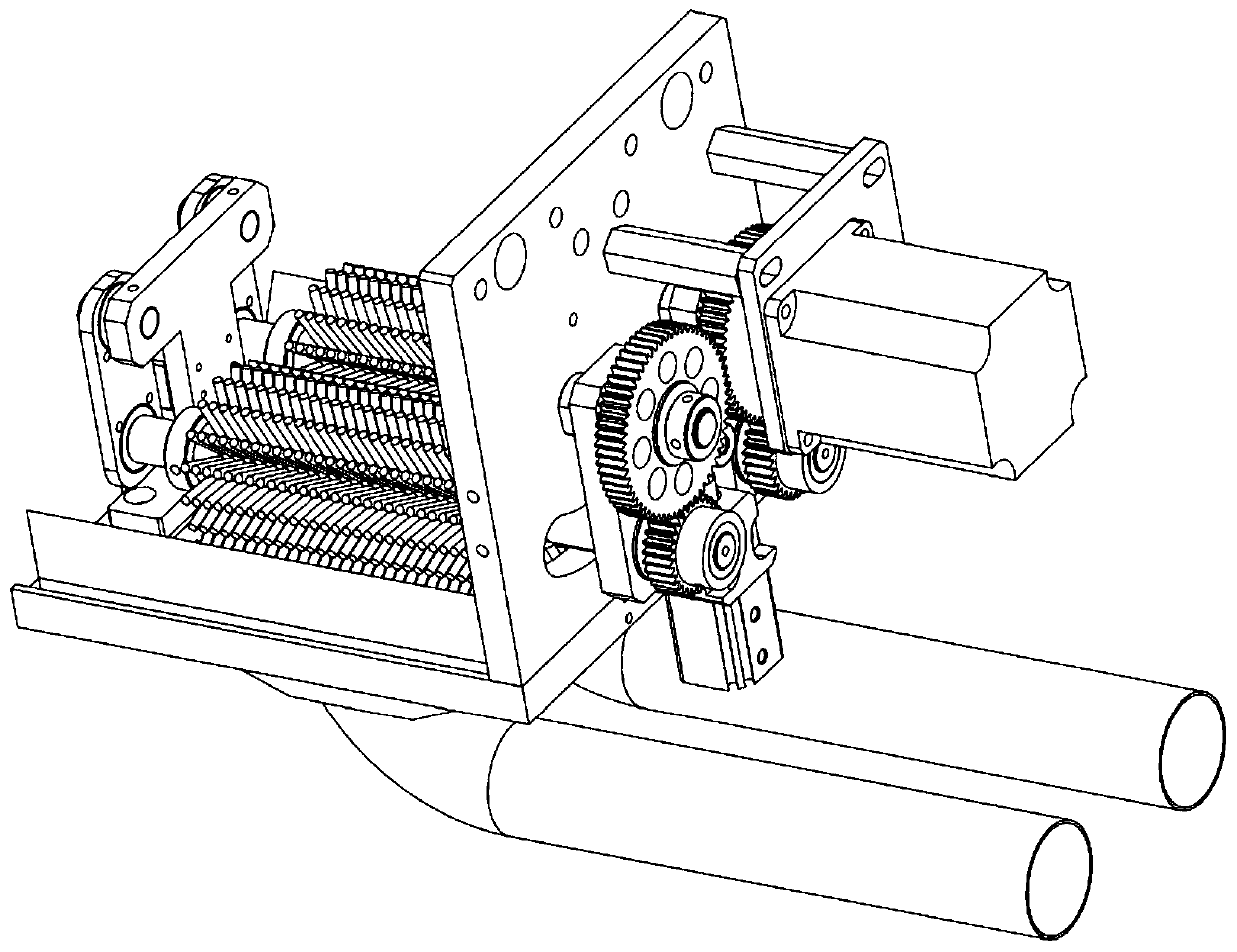
Existing pole piece dust brushing mechanism such as figure 1 As shown, the motor drives the two brushes to rotate in reverse through the gear set, and the pole piece passes through the middle of the two brushes to brush dust. This mechanism has the following defects: First, the brush wheel is opened, closed and rotated by the head of the cylinder. Drive, the brush wheel does not move symmetrically around the center line, and the left and right shaking causes uneven dust removal, and the dust removal effect is not ideal; second, the service life of the brush wheel is limited, and it needs to be replaced after a certain period of time. The existing dust brushing mechanism replaces the brush. When brushing the wheel, it is necessary to remove the whole mechanism from the whole machine and then disassemble the brushing mechanism. It is difficult and inconvenient to replace, and it takes a lot of labor and time; third, the gap between the brush box or the shield is small , not conducive to film
Method used
Image
Click on the blue label to locate the original text in one second.
Reading with bidirectional positioning of images and text.
Examples
Embodiment Construction
[0020] Below in conjunction with accompanying drawing, the specific embodiment of the present invention is described further:
[0021] In the description of the present invention, it should be noted that the terms "center", "upper", "lower", "left", "right", "vertical", "horizontal", "inner", "outer" etc. The indicated orientation or positional relationship is based on the orientation or positional relationship shown in the drawings, and is only for the convenience of describing the present invention and simplifying the description, rather than indicating or implying that the indicated position or element must have a specific orientation, and must have a specific orientation. construction and operation, therefore, should not be construed as limiting the invention.
[0022] In the description of the present invention, it should be noted that unless otherwise specified and limited, the terms "installation", "connection" and "connection" should be understood in a broad sense, for...
PUM
Abstract
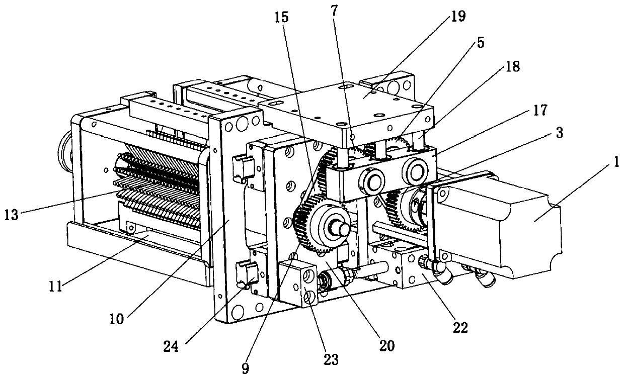
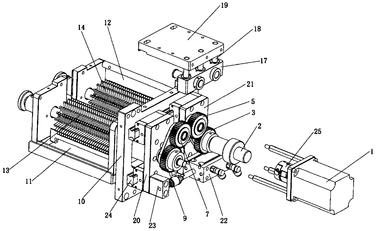
The invention relates to a pole piece ash brushing mechanism good in symmetry. A motor, a first gear shaft, a first gear, a second gear shaft, a second gear, a third gear shaft, a third gear, a fourthgear shaft, a fourth gear, a supporting plate, a left ash brushing box, a right ash brushing box, a left brush wheel, a right brush wheel, a left connecting block, a right connecting block, sliding blocks, guiding rods, an adjusting plate, a left sliding plate, a right sliding plate, an air cylinder, an air cylinder connecting head and sliding rails. The pole piece ash brushing mechanism is reasonable in integral structure design, when the air cylinder drives the left sliding plate and the right sliding plate to move towards the left-right outer sides or inner sides along the sliding rails, the corresponding sliding blocks move downwards or upwards along the guiding rods, it is guaranteed that the moving distances of a left brush wheel system and a right brush wheel system are equal and are constantly symmetric relative to the axis center lines of the two brush wheels, the ash brushing quality is improved, the structure is firm, and the ash brushing speed is high; and in addition, a pull handle mechanism is additionally arranged so that brush wheel replacement can be convenient, detachment of the whole mechanism is not needed, manpower and time are saved, and practicability is high.
Description
technical field [0001] The invention relates to the field of lithium ion battery manufacturing, in particular to a pole piece dust brushing mechanism. Background technique [0002] At present, lithium-ion film making machines and winding machines are equipped with pole piece dust brushing mechanism, which brushes the pole piece to ensure the cleanliness of the pole piece and reduce poor processing. Existing pole piece dust brushing mechanism such as figure 1 As shown, the motor drives the two brushes to rotate in reverse through the gear set, and the pole piece passes through the middle of the two brushes to brush dust. This mechanism has the following defects: First, the brush wheel is opened, closed and rotated by the head of the cylinder. Drive, the brush wheel does not move symmetrically around the center line, and the left and right shaking causes uneven dust removal and unsatisfactory dust removal effect; second, the service life of the brush wheel is limited, and it ...
Claims
Application Information
Patent Timeline
Application Date:The date an application was filed.
Publication Date:The date a patent or application was officially published.
First Publication Date:The earliest publication date of a patent with the same application number.
Issue Date:Publication date of the patent grant document.
PCT Entry Date:The Entry date of PCT National Phase.
Estimated Expiry Date:The statutory expiry date of a patent right according to the Patent Law, and it is the longest term of protection that the patent right can achieve without the termination of the patent right due to other reasons(Term extension factor has been taken into account ).
Invalid Date:Actual expiry date is based on effective date or publication date of legal transaction data of invalid patent.