
Fabricated steel welded mesh and preparation method thereof

A welded steel mesh and assembled technology, applied in the direction of online mesh, other household appliances, structural elements, etc., can solve the problem that longitudinally stressed steel bars cannot be practically applied, and achieve high practicability, flexible operation, and guaranteed construction quality. Effect

Pending Publication Date: 2019-03-26
宁波市民用建筑设计研究院有限公司
View PDF0 Cites 0 Cited by
  • Summary
  • Abstract
  • Description
  • Claims
  • Application Information

AI Technical Summary

Problems solved by technology

[0008] After adopting the above structure, the assembled welded steel mesh of the present invention has the following advantages: it overcomes the defect that the combination of longitudinally stressed steel bars in the prior art cannot be practically applied to engineering practice, and provides a method consisting of multiple single transverse steel bars and multiple pairs The longitudinally stressed steel bars, that is, the assembled steel bar welded mesh composed of parallel bars fixedly connected to each other, improves the bearing capacity of the longitudinal steel bars. The present invention can still be prepared under the technical conditions that there is no mechanical equipment capable of processing parallel steel bar welded nets. It has the characteristics of flexible clamping and flexible operation, and can realize the application of welded mesh with reinforced bars in actual engineering. It has strong practicability, which not only improves the work efficiency of the steel bar project, but also ensures the construction quality. Thus improving the engineering quality of concrete structures

Method used


Image

  • Fabricated steel welded mesh and preparation method thereof
  • Fabricated steel welded mesh and preparation method thereof
  • Fabricated steel welded mesh and preparation method thereof

Examples


Embodiment Construction

[0031] The specific embodiments of the present invention will be further described below in conjunction with the accompanying drawings. What needs to be declared here is that the descriptions of these embodiments are used to help understand the present invention, but are not intended to limit the present invention. In addition, the technical features involved in the various embodiments of the present invention described below may be combined with each other as long as they do not conflict with each other.

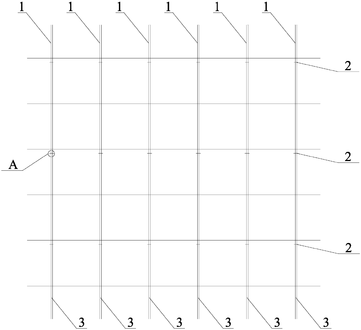
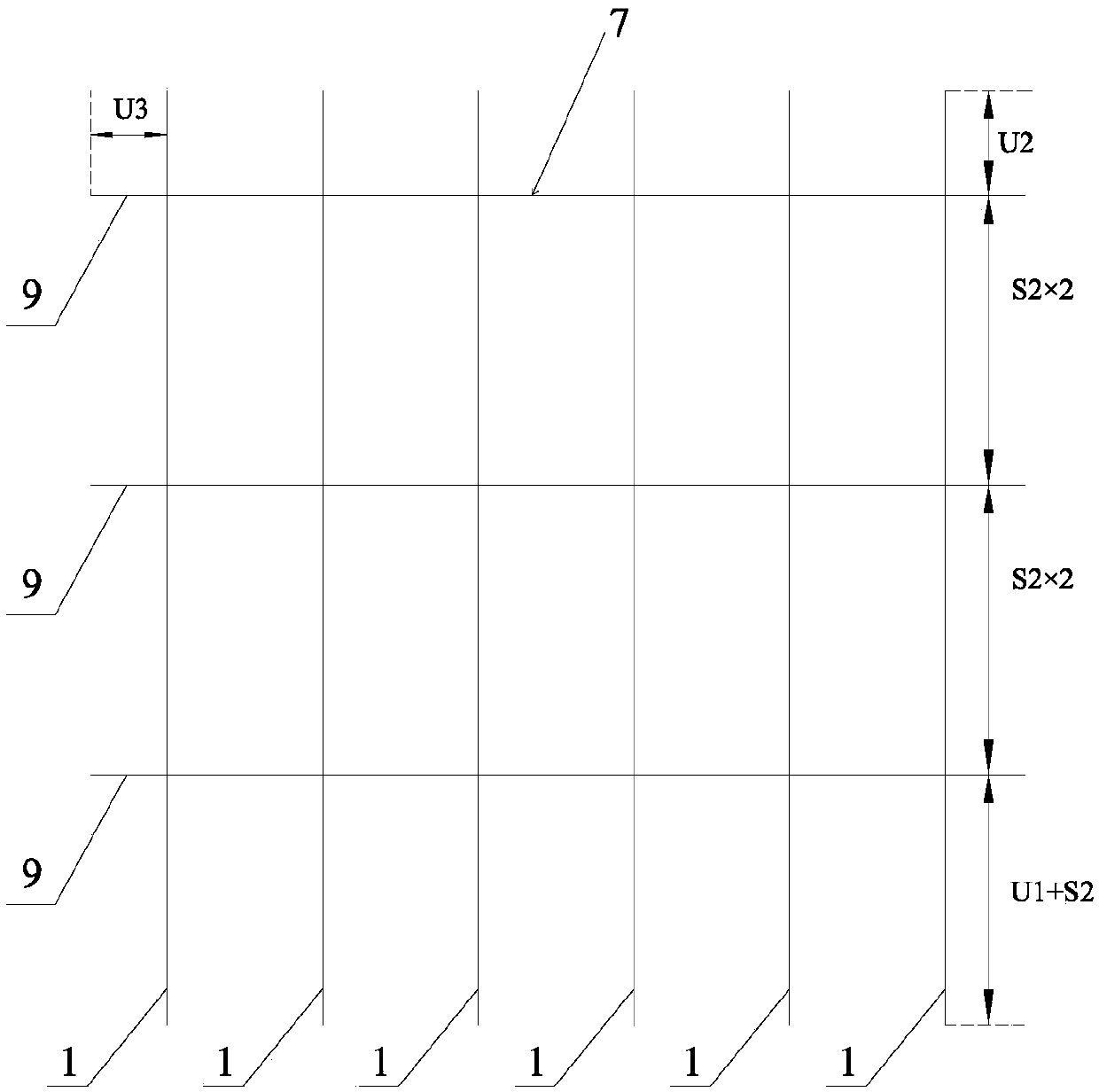
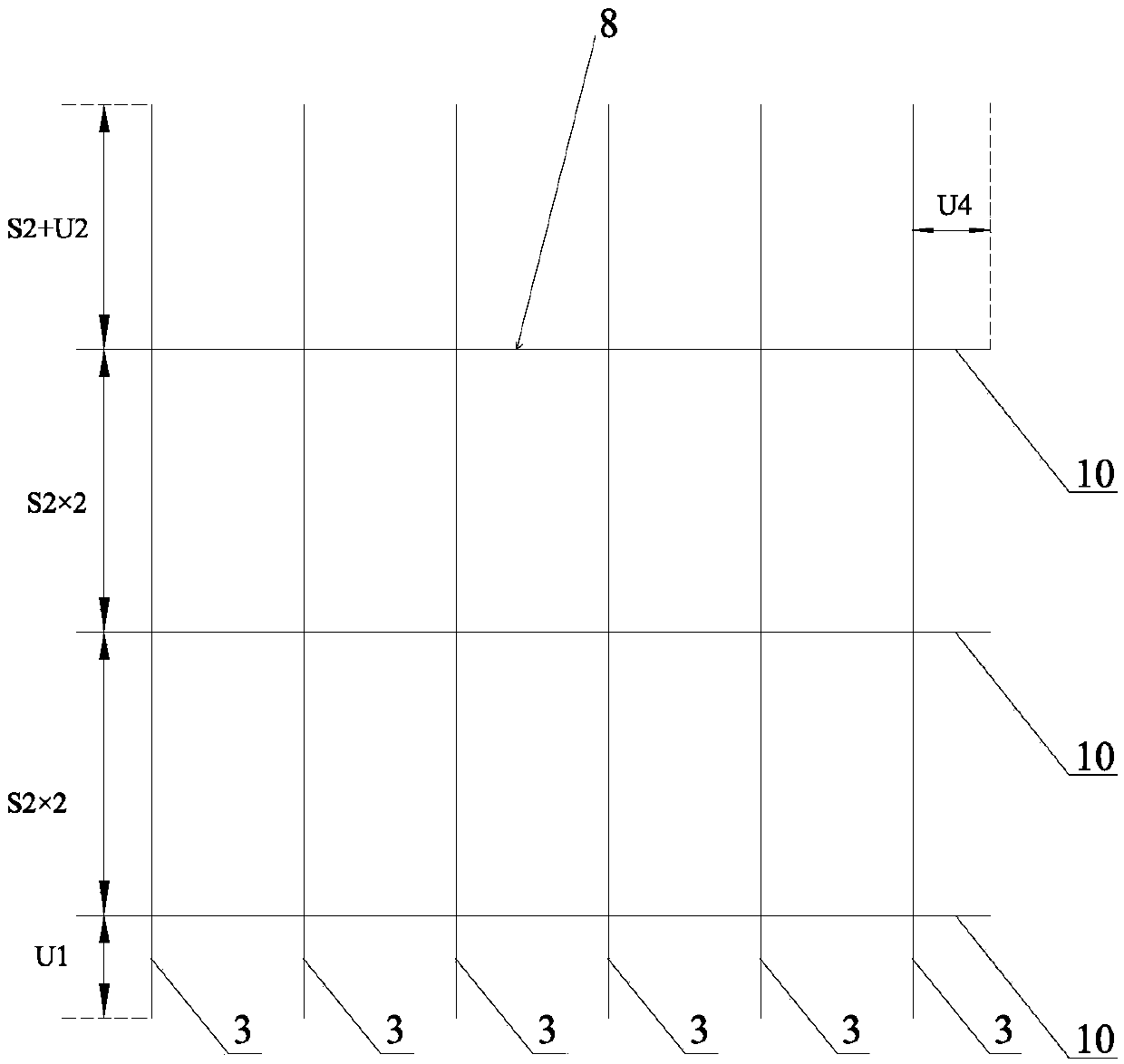
[0032] Such as figure 1 , figure 2 , image 3 , Figure 4 , Figure 5 , Image 6 , Figure 7 , Figure 8 , Figure 9 shown

[0033] The assembled welded steel mesh of the present invention comprises a plurality of transverse reinforcement bars arranged in parallel intervals and a plurality of first longitudinal reinforcement bars 1 arranged in parallel intervals. The transverse reinforcement is divided into a first transverse reinforcement 9 and a second transverse...


PUM


Abstract

The invention discloses a fabricated steel welded mesh and a preparation method thereof. The fabricated steel welded mesh comprises a plurality of transverse reinforcing bars arranged in parallel spacing and a plurality of first longitudinal reinforcing bars arranged in parallel spacing, wherein the transverse reinforcing bars are divided into first transverse reinforcing bars and second transverse reinforcing bars; the first transverse reinforcing bars are spaced apart from the second transverse reinforcing bars; each of the first longitudinal reinforcing bars and each of the first transversereinforcing bars are at right angles to each other, and intersections are welded by a row of welding torches of welding equipment to form a first half-steel welded mesh; each of the second longitudinal steel bars and each of the second transverse steel bars are at right angles to each other, and intersections are welded by a row of welding torches of the welding equipment to form a second half-steel welded mesh; an adjacent second longitudinal reinforcing bar is arranged on one side of each of the first longitudinal steel bars to be paired, and each pair of the first longitudinal reinforcingbar and the second longitudinal reinforcing bar is fixedly connected by a plurality of elastic clips. The fabricated steel welded mesh realizes the application of a parallel-bar welded steel mesh in the actual engineering.

Description

technical field [0001] The invention relates to the technical field of building steel bar processing, in particular to an assembled welded steel bar mesh and a preparation method thereof. Background technique [0002] Welded steel mesh for construction is a commonly used steel bar processing technology in civil engineering concrete structures. Generally, the longitudinal steel bars and transverse steel bars are arranged at right angles to each other with a certain size and spacing through a special tool welded mesh forming machine, or orthogonally arranged, and all The intersections are connected by piezo-resistance welding to form reticulated reinforcement products. It is generally used as stress reinforcement or structural reinforcement in large-area concrete structures such as construction projects, highway bridges, etc., such as stressed walls. Compared with the traditional binding connection processing method, this existing technology greatly improves the production ef...

Claims


Application Information

Patent Timeline
IPC IPC(8): E04C5/04B21F27/10
CPCE04C5/04B21F27/10
Inventor 吴刚
Owner 宁波市民用建筑设计研究院有限公司
Learn More