Engine combustion-supporting energy-saving device and vehicle

An energy-saving device and engine technology, which is applied to engine components, machines/engines, vehicle components, etc., can solve the problems of low fuel energy conversion efficiency and high emissions of engines, and achieve high energy conversion rate, reduced emissions, and sufficient combustion effects.

Pending Publication Date: 2019-03-26
正道新能源科技有限公司
View PDF0 Cites 2 Cited by
  • Summary
  • Abstract
  • Description
  • Claims
  • Application Information

AI Technical Summary

Problems solved by technology

[0005] The purpose of the embodiments of the present invention is to provide an engine combustion-supporting energy-saving

Method used


Image

  • Engine combustion-supporting energy-saving device and vehicle
  • Engine combustion-supporting energy-saving device and vehicle
  • Engine combustion-supporting energy-saving device and vehicle

Examples


Example Embodiment

[0033] Example 1

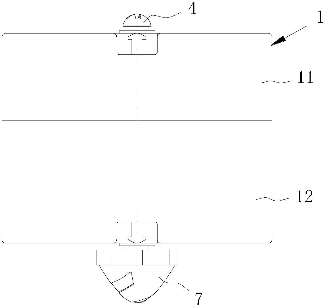
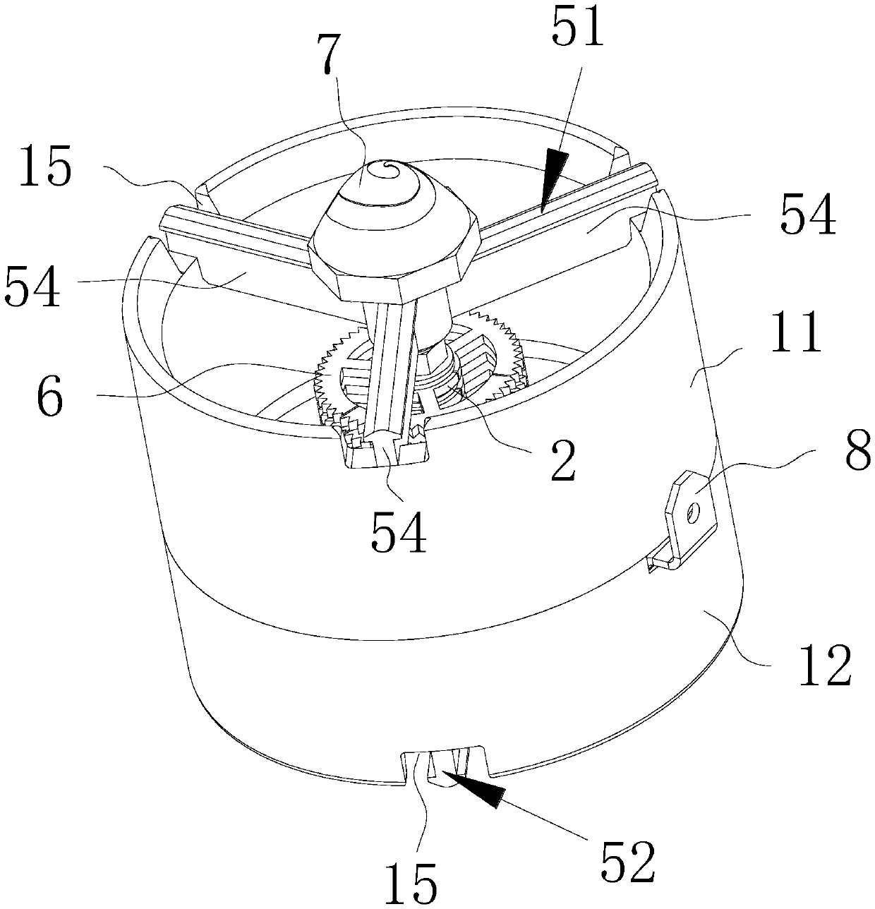
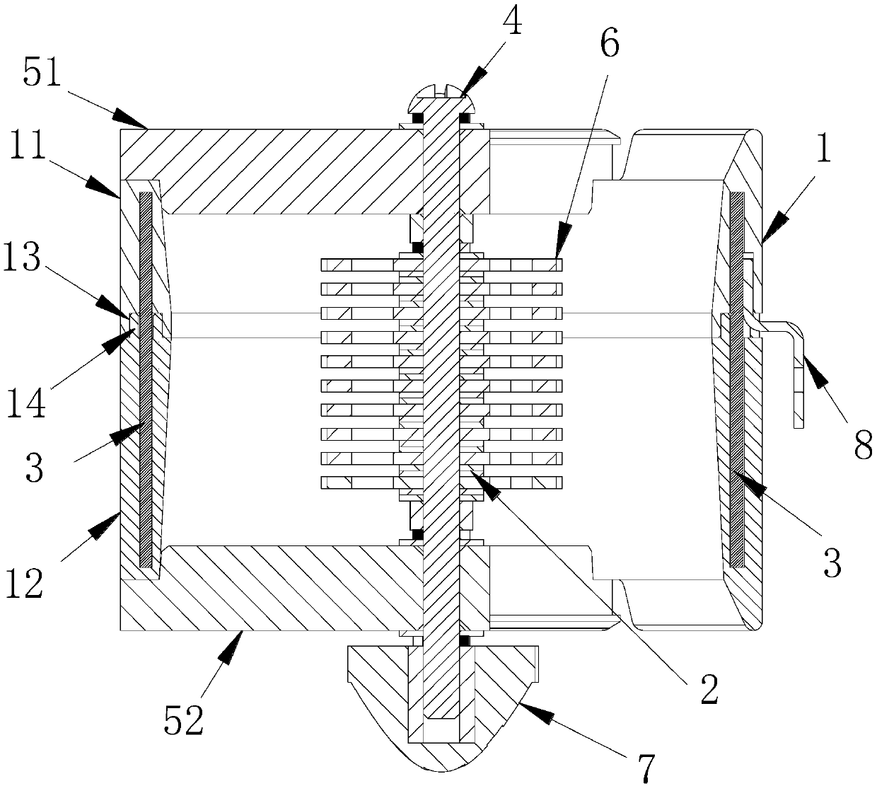
[0034] This embodiment provides an engine combustion-supporting energy-saving device. like Figure 1-3 As shown, the engine combustion-supporting energy-saving device includes a housing 1, a first electrode 2, a second electrode 3, a conductive shaft 4, a bracket and a gear ring 6; wherein,

[0035] The shell 1 is made of flame retardant material. The casing 1 includes an upper casing 11 and a lower casing 12, and the upper casing 11 and the lower casing 12 are stacked in the axial direction of the casing. In order to facilitate the positioning of the upper case 11 and the lower case 12 and to improve the stability of the upper case 11 and the lower case 12, grooves 13 and protrusions are respectively arranged on the overlapping surfaces of the upper case 11 and the lower case 12. The platform 14 matches the groove 13 and the boss 14 , and the upper casing 11 and the lower casing 12 are plugged together through the groove 13 and the boss 14 . When the gr...

Example Embodiment

[0045] Example 2

[0046] This embodiment provides a vehicle, which includes an intake pipe, a throttle valve, a combustion-supporting energy-saving device, and a high-voltage power supply. The intake pipe communicates with the throttle valve, and the combustion-supporting energy-saving device is arranged in the intake pipe. In the energy-saving device, the two ends of the high-voltage power supply are respectively electrically connected to the first electrode and the second electrode. For the specific structure of the engine combustion-supporting and energy-saving device, refer to Embodiment 1, which will not be repeated here.

[0047] In this embodiment, the high-voltage power supply includes a vehicle-mounted DC power supply and a transformer, the output terminal of the vehicle-mounted DC power supply is electrically connected to the input terminal of the transformer, the output terminal of the transformer is electrically connected to the input terminal of the positive and ...


PUM


Abstract

The embodiment of the invention discloses an engine combustion-supporting energy-saving device and a vehicle. The engine combustion-supporting energy-saving device comprises a shell, a first electrode, a second electrode, a conductive shaft, a support and a toothed ring, wherein the conductive shaft is fixed into the shell through the support; the toothed ring is fixed onto the conductive shaft; one end of the conductive shaft stretches out of the shell; the first electrode is arranged on the conductive shaft and is located in the shell; the second electrode is embedded into the wall of the shell; and the first electrode and the second electrode are electrically connected with an output end of a high-voltage power supply and are made of carbon fiber materials. According to the engine combustion-supporting energy-saving device, static charges in air and oil gas are effectively eliminated, and air and a fuel are sufficiently mixed uniformly, so that the combustion efficiency of the fuelis improved, the utilization rate of the fuel oil is improved, and the emission load is reduced.

Description

technical field [0001] The invention relates to the technical field of engines, in particular to an engine combustion-supporting energy-saving device and a vehicle. Background technique [0002] Both vehicle engines and thermal generators use fuel (such as fuel oil or natural gas) as energy sources to convert chemical energy into kinetic energy or electrical energy. Whether the fuel can be fully burned directly affects the fuel energy conversion efficiency of the engine, and at the same time affects the emission of pollutants. [0003] In order to improve the fuel energy conversion efficiency of the engine and reduce emissions, relevant technical personnel have developed technologies such as electronic injection, exhaust gas turbo air charging, electric turbo air charging and plug-in hybrid (PHEV), but the effect is still not ideal. [0004] Relevant technical personnel have developed a kind of energy-saving environmental protection device, and it is that negative ion cerami...

Claims


Application Information

Patent Timeline
IPC IPC(8): F02M27/04B60R16/03
CPCF02M27/042B60R16/03
Inventor 仰宝真尹树生张宇
Owner 正道新能源科技有限公司
Why Eureka
Try Eureka